| Machine Menu | ||
|---|---|---|
 |
Chapter 5. Mill |  |
| Machine Menu | ||
|---|---|---|
| |
Chapter 5. Mill | |
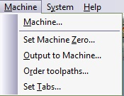
Figure 5.52. Machine Menu
Abstract
The main milling menu in Mill and is used to create and send toolpaths to the machinery. The machining process utilizes the tools defined in the Setup menu and allows you to define and create toolpaths (Face Mill, Slot, Profile, Area Clear and Drill Cycles). Toolpaths can then be sent directly to the machine, or saved as a file.
 |
Start the Machine wizard that will proceed with a step-by-step guide to complete your job. The list below describes the order of the Machine Wizard:
Figure 5.53. Example Machine Wizard Screen 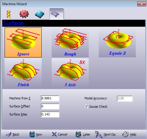 While working through the Wizard you can edit or add parameters in any of the four tabs: Tool, Technology, Strategy and Surface. In addition to the tabs placed at the top of the wizard screen, there is a row of six buttons that exist in all tab modes:
|
Tool .
Figure 5.54. Tool
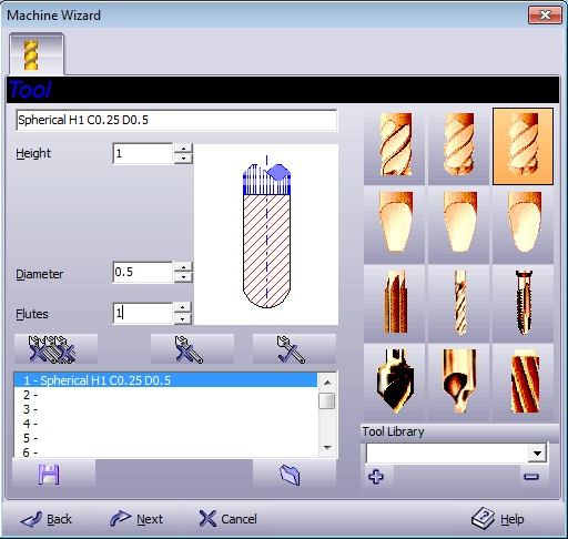
Tools define the tools to be used in the machining process. An engraving tool may have a conical cross section with a nose tip radius and a corner radius. Many kinds of shaped or tapered engraving tools can be defined including flat, ball, and tapered tools.
Technology . Creates a toolpath with tool compensation.
Figure 5.55. Technology
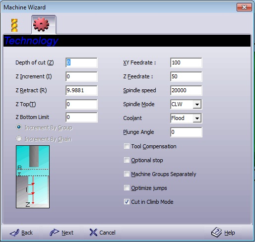
| Depth of cut (Z) | Final depth you want to reach in the material with respect to the Z Top value. |
| Z Increment (I) | Input the increment by which the milling should occur on the Z-axis. |
| Z Retract(R) | Sets the safe retract plane above the material and clamps or other objects so that the cutter moves about freely. This value is absolute. |
| Z Top (T) | Sets the local zero plane (the level at which the material surface top plane was set). Usually Z Top is set at zero. |
| Increment by Group | Executed over groups according to the value in the window; therefore the Z level is uniform. This method is time-consuming. |
| Increment by Chain | Applied on chains according to the value in the window. The cutting tool finishes a chain and then passes to the next chain. This method is more efficient than the By Group method because less machine time is needed. |
| XY Feedrate | Enter the machine's feed rate (units/min) for the horizontal (XY) plane. |
| Z Feedrate | Enter the machine's feed rate (units/min) for the vertical (Z) axis. This defines the speed of entry into material. |
| Spindle speed | The cutting tool's rotation speed is rated in revolutions per minute (RPM). |
| Spindle Mode |
Select the cutting tool's rotation direction:
|
| Coolant |
Select the applied cooling method:
|
| Plunge Angle | Entrance angle of the tool to the material. |
| Tool Compensation |
|
| Optional stop | Machine will pause each time the machining process completes a single marked group and waits for the operator to resume command on the machine panel. |
| Machine Groups Separately | Machine each marked group on its own. This feature is useful for groups created by the GraphiCAD stack function (serial numbers, nameplates, etc.). |
| Optimize Jumps | Optimize the rapid motions. The system default is off in order to enable the system to machine from inside out. If it is necessary to minimize the jumps, you may turn the switch on, so that the shortest way is calculated. |
| Cut in climb mode | Unless checked, cutting is done in normal mode. |
Strategy . There are five toolpath strategies to select from – Profile, Area Clear, Slot, Drill or Face.
Profile .
Figure 5.56. Strategy - Profile
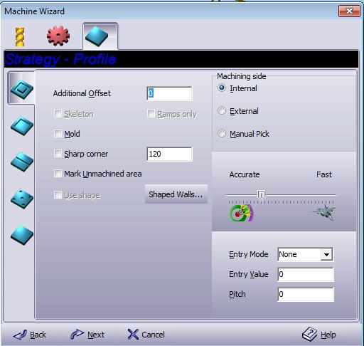
| Skeleton | Tapered tool will travel to the maximum allowed depth in cases of close proximity entities. |
| Ramps only | Only active if Skeleton is checked. By-passes the profile milling process of Skeleton. Thereby saving time if the tapered tool has already fulfilled its milling operation. |
Area Clean .
Figure 5.57. Strategy - Area Clean
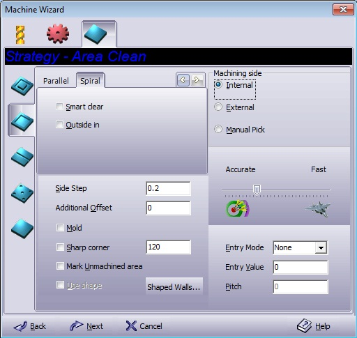
Figure 5.58. Parallel

Select Hatch Angle to clear the area in parallel sweeps, and enter the angle (in degrees) at which the area clear (X-hatch) operation will take place. A value of 0° defines the horizontal X-hatch lines; a value of 90° defines the vertical hatch lines. Spiral/Parallel is calculated for all the marked groups as if the groups are one object.
Optimized – for a smart bi-directional move, with minimum movement of the tool in the Z- level.
Uni-Directional – for machining in only one direction.
Bi-Directional – For machining in two directions.
Laser mode – as Optimized, without connecting the moves in order to avoid double burn by the laser.
Figure 5.59. Laser mode | Bi-Directional | Uni-Directional | Optimized

| Profile pass |
Select one of the following mode:
|
Figure 5.60. Spiral

Clear the area in a spiral pattern.
| Smart clear | When side step value is set to more than 50% of the tool’s diameter size. When selected, the program creates a supplementary toolpath - Smart clear to cover the unmachined areas remaining due to the large side step selected. Use of this option for less than 50% side step will not create the Smart clear toolpath. This is a powerful tool and vital for creating pockets and other area cleaning assignments in a fast and accurate manner. |
| Outside in | Change the usual milling direction of inside out. |
Profile / Area Clean Common .
Side Step
|
Defines the distance (in units) between two adjacent tool moves. | |||||||||||
| Additional Offset | Extra stock in addition to the original geometry stock, necessary for finishing. | |||||||||||
| Mold | Sets the procedure to create a toolpath on the contour projected at the Z depth value. This option is effective when a tapered tool is used. | |||||||||||
| Sharp Corners | Corners consist of straight lines unless there is an intersection between two entities. In that case, the corners will be chamfered. Enter the desired offset in the adjacent text box. | |||||||||||
| Mark Unmachined area |
There are often unmachined areas after cutting because the selected tool was too large to clean the entire area. This option creates a new group consisting of the unmachined area. Select a smaller tool, mark the unmachined group, and activate the Profile (or Area Clear) option again.
|
|||||||||||
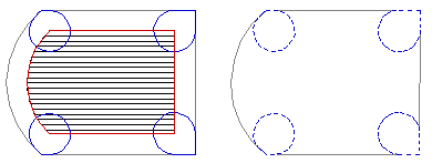
| Shaped Walls |
Figure 5.61. Tool 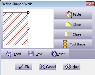 By dragging on the circular control points you can manually design the shape of a wall.
You are able to save and load previously created shaped wall. Resetting returns the shaped wall back into its original position.
|
|||||||||||
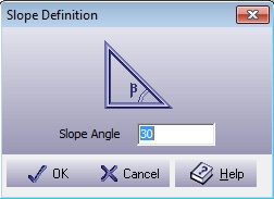
| Entry Mode | Select one of the following three entry modes:
|
|||||||||||
| Entry Value | Defines the distance between the middle of the first
entity chosen and the first tool entry location. Circular entry mode - the
distance is the radius of the half circle. If the value is larger than
the geometry width, the Entry Value
is set automatically to optimal value – the entry point will
not move to another location. |
|||||||||||
|
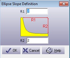
Pitch
|
Defines the down step on every complete circle. The helical motion is similar to the action of inserting a screw, with a fixed pitch. | |||||||||||
| Machining side | Sets the offset side with respect to the marked groups. This value is calculated for all the marked groups as if the groups are one object. Select Internal to apply the offset on the inner side of the object, External to apply the offset on the outer side of the object, or Manual Pick to apply the offset manually on the screen. If the marked geometry consists of open contours, Left and Right options replace the Internal and External options. | |||||||||||
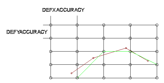
| Accurate/ Fast | Controls the calculation speed – as opposed to the calculation accuracy. The default value assures very high accuracy. However, in some cases, such as very small objects, higher accuracy is required. A good practice is to machine the rough toolpath with low accuracy (fast), in order to reduce processing time. | |||||||||||
Slot .
Figure 5.64. Strategy - Slot
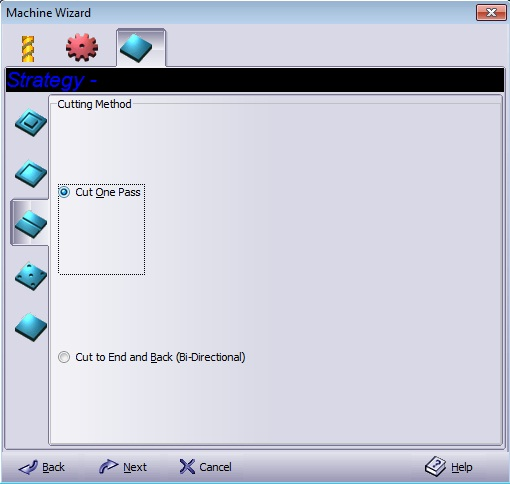
Toolpath that cuts directly on a contour.
| Cut One Pass | Slot machines the geometry once only. |
| Cut to End and Back (Bi-Directional) | Slot the geometry from start-to-end of each contour and then repeat from end-to-start, thereby ensuring high quality. |
Drill .
Figure 5.65. Strategy - Drilling cycles
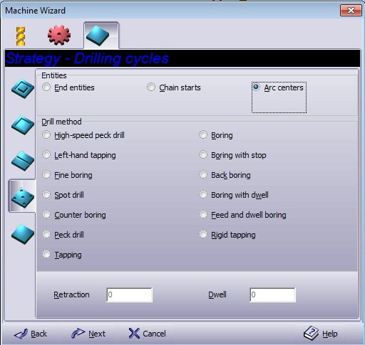
Create drilling toolpath. The entry windows for Retraction and Dwell parameters will appear according to the parameters that were requested for the specific drill method.
| End Entities | Drilling the end edges of the entity. |
| Arc Centers | Drills the center of each arc that belongs to the marked group. |
| Chain Starts | Drill a preparation hole for the milling tools after using Area Clean. The location of the hole depends on the Area Clean method (Spiral, Parallel). |
Figure 5.66. End Entities | Arc Center | Chain Starts

Table 5.1. Drill method
| Method | Drilling (-Z direction) | Operation at the bottom of the hole | Retraction (+Z direction) |
|---|---|---|---|
| High-speed peck drill | Intermittent feed (forward and backwards drilling). | Rapid traverse rate (the rate of fast traverse movement). | |
| Left-hand tapping | Continuous feed (with no stopping) | Spindle CW (rotation clockwise) | Continuous feed |
| Fine boring | Continuous feed | Oriented spindle stop[a] + Dwell | Rapid traverse rate |
| Spot drill | Continuous feed | Rapid traverse rate | |
| Counter boring | Continuous feed | Dwell | Rapid traverse rate |
| Peck drill | Intermittent feed | Rapid traverse rate | |
| Tapping | Continuous feed | Spindle CCW (rotation counterclockwise) | Continuous feed |
| Boring | Continuous feed | Continuous feed | |
| Boring with stop | Continuous feed | Spindle stop | Rapid traverse rate |
| Back boring [b] | Continuous feed | Spindle stop | Rapid traverse rate |
| Boring with dwell | Continuous feed | Dwell + Spindle stop | Rapid traverse rate |
| Feed and dwell boring | Continuous feed | Dwell | Continuous feed |
| Rigid tapping | Continuous feed | Continuous feed | |
|
[a] Because a spindle-oriented stop is performed at the bottom of the hole, and the spindle retracts after shifting in the direction opposite the cutter direction, high precision and efficient boring is performed without scratching the machined part surface. [b] In this method, after the tool is positioned along the X and Y-axes, the spindle stops at the orientation position. The spindle is then shifted in the direction opposite the tool and is positioned at the bottom of the hole at the rapid traverse rate. At this position, the tool returns only for the shift value, and the spindle rotates clockwise. |
|||
All the drill cycles conform to the ISO standard as defined by Fanuc™ Ltd.
| Retraction | Sets the retraction distance for the cutting tool moves. Use this option to simplify chip disposal and perform efficient machining. Retraction is performed at the rapid traverse rate. |
| Dwell | Enter the delay time at the bottom of the hole (in seconds). |
Face .
Figure 5.67. Strategy - Face milling
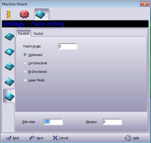
Create a cleaner and smoother area on the billet.
Parallel .
Figure 5.68. Parallel

Please refer to Area Clean for information.
Parallel .
Figure 5.69. Radial

Select Round or Square to get a snail like toolpath.
| Width/ Height | Radial dimensions. |
| Snail Center point X/ Y | The X/ Y coordinate of the radial center. |
Please refer to Area Clean for information.
Parallel/ Radial Common .
| Side Step | Please refer to Side Step. |
| Margin | Adds an offset to the billet size. |
Figure 5.70. Surface
Select the desired reference to surfaces.
Ignore - does not refer to the surfaces in the job, if any.
Rough - leaves a rough surface finish (fast machining). The machine movement is with straight Z levels, and no jumps.
Equal Z - engraves between the border of a protruding surface and the border of a billet with minimal jumps.
Finish - leaves a fine surface finish. The machine movement follows the surface shape.
5 Axis - this option creates a 5-axis toolpath. The toolpath contains also the i,j,k normal values at the tool tip. These values are available when posting the file to a 5-axis machine.
It is preferable to start with the Rough option while giving some extra offset for the tool and then continuing with the Finish option until the required height is achieved.
| Machine from Z | Defines the Z level in which the machine starts to engrave. This is a top level limitation as well. The default value is the billet top. For surface milling, verify that this value is above the marked surfaces. Otherwise only parts of the intended toolpath may be visible and active. | |||
| Surface Offset | Extra stock in addition to the original geometry stock. | |||
| Surface Step | Defines a grid sampling rate on the surface that represents the tool movement. Smaller values create a denser grid that results in a better surface quality; this however, also increases the calculation period. | |||
|
Model Accuracy
|
Grid accuracy for calculating the border of a protruding surface and the border of a billet. | |||
| Gouge Check |
If marked, the toolpath is calculated with the compensation of the tool’s shape. If not marked, all the toolpath calculations are with respect to the tool’s tip. The default value for Gouge Check may be set in the system options. Figure 5.71. Gouge Check marked | Gouge Check unmarked 
|
 |
Change the coordinate system origin location. Use the mouse to move the cursor to the desired location and press the button to set the new origin (for details on precision clicking, see Clicking Around with Cursors in the introduction chapter). The coordinate system can be moved in three dimensions, and the new location will serve as the new machine zero for toolpath calculations. |
 |
In order to machine the tool path created in the operation, the toolpath must be post-processed in the code required to drive the machine. Any group on the layout may be marked to be sent to the machine and cut. The communication may be implemented directly or by file transfer. The G-Code parameters are set in the Create Machine Program dialog box. Figure 5.72. Create Machine Program, Machine Tab Dialogue 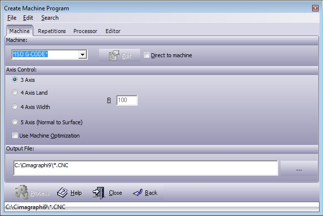
Figure 5.74. Create Machine Program, Repetition Tab Dialogue 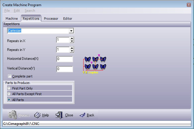
Figure 5.75. Create Machine Program, Processor Tab Dialogue 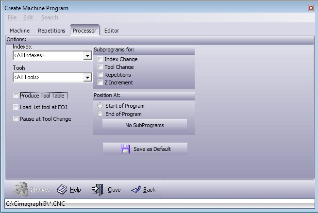
Figure 5.76. Create Machine Program, Edit Tab Dialogue 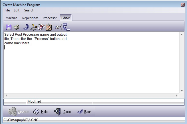
|
 |
Often it is necessary to re-organize the toolpath sequence before sending toolpaths to the machine. Cimagraphi provides several ways to order the toolpaths. Selecting this menu item will display the Order Toolpath dialog box. Figure 5.77. Order Toolpaths Dialogue 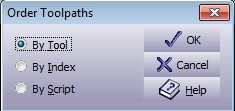
|
 |
In order to leave the part attached to the billet, little jumps in the toolpath are created - Tabs. Figure 5.78. Tab Settings Dialogue 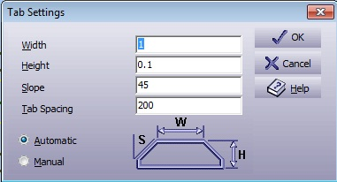
|
| |
 |
|
| Surface Menu |  |
System Menu |


![[Note]](../images/note.png)