Surface Menu

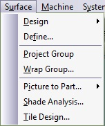
Figure 5.34. Surface Menu

Surface menu

SurfaceDesign

Surface → Design→  Ruled Surface

Emboss ruled surface

The Emboss Ruled Surface function is similar to the Emboss command. A characteristic cross section will be applied on the area bounded by the 2D group. A group may contain one or more contours. To activate select Emboss Ruled Surface from Component menu or click on the relevant icon. A wizard will walk you through the process of creating the ruled surface.

Surface Type. 

Figure 5.35 Wizard Page 1, Surface Type

Wizard page 1, surface type

We can select from creating a surface from a single flow line (I), creating a surface from two flow lines (II), and creating a surface from two flow lines and a Z guide line (III).

Surface from: I,II,III Picture: Method: Restrictions:
Single flow line. ruled single We need to define single flow line by clicking on it on the screen. None, even from a regular line we can make a ruled surface
Two flow lines. two flows We need to select two different flow lines. We must have two different flow lines in separate layers.
Two flow lines and a z guide line. 2 flow with z We need to select two different flow lines and an embossed flow line as z guide line. We must have two different flow lines in separate layers, and an embossed part for Z guide line.

First we need to click on the flow line we need, afterwards we can select a starting point by clicking on the "set flow line starting point button".ruled surface starting point 

Another option we can use is to set the flow line direction by clicking on the button ruled surface direction 

This is how the start point and the direction looks like:ruled surface exmp 

After we finished setting up the flow line we will press next and receive the parameters page

parameters,

Figure 5.36. Wizard Page 2, Parameters

ruled surface param

The parameters we can use are:

Section alignment: normal alignment or vertical alignment.

Contour type: the contour type we use lines or curves.

Edges: the surface edge from upper right to left, upper left to right and center.(in two flow lines and two flow lines with a z guide line we have only the center edge)


Figure 5.37. Wizard Page 2, sections

ruled surface sections

On the sections part we can choose how our surface sections will look like.

We can copy a section to use or use an old section we used by copying it and paste it on the section preview, after every change we made on the section preview we need to press on apply button .ruled surface apply

We can also save the section we used so we can use it later on a different project.

These buttons written under display the capabilities of creating a surface by placing sections as we require and we can use different sections on the same part.

Button Image: Definition: Comments:
ruled pick Pick section.
ruled add Add Section After we choose add section we need to click on the flow line.
3.jpg Remove section After we choose remove section we need to click on the place we want it to delete.
4.jpg Remove all sections
5.jpg Break flow line to add section. Adds a new point on the flow line.
6.jpg Swap entity type.

When the section we wish to add is ready we just need to add him to the surface by using the marking on the flow lines, afterwards we will directly receive the result.

and don't forget we can always remove the section if the result is no good for us.

SurfaceDesignRevolve

Revolve

This option is used to create a surface of revolution. The section to be revolved is the marked group from the Group List. The following dialog box appears:

Figure 5.38. Revolve Dialogue

Revolve dialogue

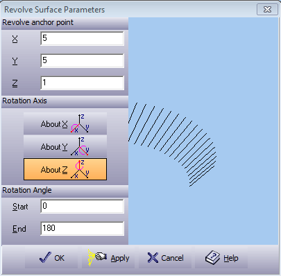
A preview of the rotation section will appear in the box on the right. While editing this dialog box, use View options to preview the design before accepting it.

Revolve anchor point The anchor point of the axis of rotation. Enter in a value for the revolving anchor points on the X, Y, and Z-axes.
Rotation Axis Choose a rotation axis from the three choices.
Rotation Angle

Start Determines the coverage of the body surface. Enter a starting angle.
End Determines the coverage of the body surface. Enter an end angle.

Apply
Apply the changes you made to the preview window.

Press OK to create an rotation surface. Exit without changes by pressing Cancel. Press Help to open the On-line Help.

SurfaceDesignExtrude

Extrude

To create a drive for a surface, select Extrude from the Design Surface in the Surface menu. The section to be extruded is the marked group from the Group List. The following window appears:

Figure 5.39. Extrude Dialogue

Extrude dialogue

A preview of the extrude section will appear in the box on the right. While editing this dialog box, use View options to preview the design before accepting it.

Drive Start Enter in a value to begin the drive point.
Drive End Enter in a value to end the drive point.
Apply
Apply the changes you made to the preview window.

Press OK to create an extrusion surface. Exit without changes by pressing Cancel. Press Help to open the On-line Help.

SurfaceDefine

Define surface

Create mathematically definable surfaces. Select this menu item to create the following surfaces through the simple dialog box:

  • Spherical: A sphere.

  • Cylindrical: A cylinder that it's main axis is parallel to the X or Y axis.

  • Conical: A trimmed cone that it's main axis is parallel to the X or Y-axis.

  • Function: Define your own surface using math functions in either cartesian or polar coordinate system.

  • Plane: A rectangular patch of a non-vertical planar surface.

  • Ellipsoid: An ellipsoid.

  • Toroid: A torus.

  • Dual radius surface: Two radii define this surface in the XZ and the YZ planes.

The Range section in the dialog sets the surface boundaries. The range is rectangular, except for the function polar system where the range may be defined by different angle/radius:

Figure 5.40. Define Surface Range Input

Define surface range input

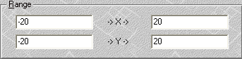
Define the range of minimal and maximal -> X -> and -> Y -> values to define the patch limits. Press OK to accept the setting for the surface. Exit without changes by pressing Cancel. Press Help to open the On-line Help.

Spherical Surface. To define a spherical surface, select Sphere tab. The Define surface dialog box should look like the dialog box below.

Figure 5.41. Define Surface Sphere Dialogue

Define surface sphere dialogue

Top Defines the surface as convex.
Bottom Defines the surface as concave.
Sphere Center These coordinates define the sphere's center point. Set the Z value so that the surface is easy to setup later on the machine.
R Defines the radius of the sphere.

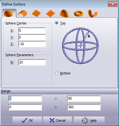
Conical and Cylindrical Surface. To define a conical or cylindrical surface, select the Cone tab. The following dialog box appears:

Figure 5.42. Define Surface Cylinder Dialogue

Define surface cylinder dialogue

Top Defines the surface as convex.
Bottom Defines the surface as concave.
X axis/Y axis Defines the axis along which the cone lies.
Cylinder Center Defines the cone's center point. Set Z so that the surface is easy to setup later on the machine.
R1 Defines the radius of the cone.
R2 Defines the second radius of the cone. Let R1 = R2 to define a cylinder. Let R2 = 0 to end the cone at a point.
L Defines the distance between the ends of the cone.

Figure 5.43. Cone on X-Axis, Bottom

Cone on X-Axis, Bottom

Function Surface. To define a surface by a function, select Function tab. This option creates a surface by interpreting the given mathematical function. The following dialog box appears:

Figure 5.44. Define Surface Function Dialogue

Define surface function dialogue

Function Name This field is the user description of the function. To change a given name simply use the function name Edit box at the top of the dialog box.
Function

This field is the actual function that will generate the surface. To edit a function, use the Function Edit box at the top of the dialog box. This field is the active function, regardless of which item is marked in the list of pre-defined functions. A function can be either Polar or Cartesian. Enter the function Z= f(X,Y) or Z= f(R,A).

The function supports the following operators :

+ Plus
- Minus
* Multiply
/ Divided
^ Power
ASIN Arc Sinus
ACOS Arc Cosine
ATAN Arc Tangent
SIN Sinus
COS Cosine
TAN Tangent
LOG Log
EXP Exponent
SQR Square root
ABS Absolute
INT Round to closest integer

[Note] Note

Make sure to open and close the correct number of brackets to achieve correct results.

Examples: Cartesian Polar
SQR(X^2+Y^2)*SIN(X/1000) COS(A)+8*LOG(R)
COS(X)*EXP(SQR(Y)) SQR(R/3)

Range These coordinates define a rectangular area in the XY plane or circular area in the RA plane. Enter the limits of these surfaces.
Save
Save a new function or to overwrite an existing function. The system stores each function in a separate file (*.fun). These files should be stored in the systems directory.

Planar Surface. To define a planar surface, select Plane tab. The following dialog box appears:

Figure 5.45. Define Surface Planar Dialogue

Define surface planar dialogue

P1

Coordinate of first point for plane definition.

X X Coordinate.
Y Y Coordinate.
Z Z Coordinate.

P2

Coordinate of second point for plane definition.

X X Coordinate.
Y Y Coordinate.
Z Z Coordinate.

P3

Coordinate of third point for plane definition.

X X Coordinate.
Y Y Coordinate.
Z Z Coordinate.

Range These coordinates define a rectangular area in the XY plane or circular area in the RA plane. Enter the limits of these surfaces.

[Note] Note

Make sure that the 3 points create a surface. For example, make sure all three points differ one from one another, and that they are not aligned.

Ellipsoid Surface. To define an ellipsoid surface, select the Ellipsoid tab. The following dialog box appears:

Figure 5.46. Define Surface Ellipsoid Dialogue

Define surface ellipsoid dialogue

Ellipsoid Center

X, Y, Z Represents the ellipsoid center.

Ellipsoid Parameters

Rx, Ry, Rz Defines the 3 radii of the ellipsoid. Keeping all three radii equal will create the perfect sphere.

Top Defines the surface as convex.
Bottom Defines the surface as concave.

Toroid Surface. To define a toroid surface, select the Toroid tab. The following dialog box appears:

Figure 5.47. Define Surface Toroid Dialogue

Define surface toroid dialogue

Toroid Center

X, Y, Z Represents the toroid center.

Toroid Parameters

R1 Defines the inner radius of the toroid.
R2 Defines the radius of the toroids in the inner tube.

Top Defines the surface as convex.
Bottom Defines the surface as concave.

Dual Radius Surface. To define a dual radius surface, select the Dual Radius tab. The following dialog box appears:

Figure 5.48. Define Surface Dual Radius Dialogue

Define surface dual radius dialogue

Peak

X, Y, Z Defines the peak or epi-center of the dual radius surface.

Parameters

Rx Defines the radius in the X-axis. The value may be positive or negative.
Ry Defines the radius of the Y-axis. The value may be positive or negative.

SurfaceProject Group

Project group

Project marked groups on either a single or group of surface(s). A new group containing the projected entities is created.

[Note] Note

A billet must be defined.

SurfaceWrap Group

Wrap group

Select this option from the Surface menu to wrap a complete geometrical group.

Figure 5.49. Wrap Parameters Dialogue

Wrap parameters dialogue

Linear Keep the original group shape in the selected line and wrap the rest of the group on the surface. Enter the Angle of the line and the reference point.
Composite Hold the group on a certain point and wrap the group over the surface.
Radial Holds an arc of the original group attaches it to the surface and wraps the rest of the group radial to the arc. Enter the Radius of the arc to attach it to the group.
Anchor Select an anchor point.
Pick manual reference point Enter the selected point's coordinates in the X, Y edit boxes, rather than selecting an anchor.

[Note] Note

A billet must be defined.

SurfacePicture to Part

SurfacePicture to PartExport Surface

Export to P2p

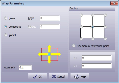
Export a surface to Picture to Part. This option enables the Picture to Part to begin the sculpting process on an existing surface. Extract to P2P dialog box shown below:

Figure 5.50. Export to P2p Dialogue

Export to P2p dialogue

Align to Place the reference point on the Align to rectangle or enter the coordinates for the reference point in the X,Y, and Z fields.
Height Enter the height of the object.
Width Enter the width of the object.
Accuracy Enter the required grid accuracy in units.
Surface
Surface
Automatically update the dialog with the external dimensions of the selected surface.

SurfacePicture to PartWeld

Weld
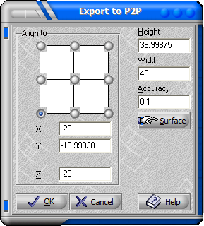
Calculates the intersection between Picture to Part surfaces and other surfaces. Depending on the Default Machine Plane, all the surface beneath or above the intersection line will be deleted.
SurfaceShade Analysis

SurfaceTile Design

Tile design

A wizard for ceramic tile creation. Uses the Shade Analysis function.

Mark the geometry of the tile. Select the SurfaceTile Design command:

Figure 5.51. Tile Design Dimensions Dialogue

Tile design dimensions dialogue

Width Width of the texture.
Height Height of the texture.
Male Creates a tile.
Female Creates the mold for the tile.
Anchor Reference point.
Position Reference point position.

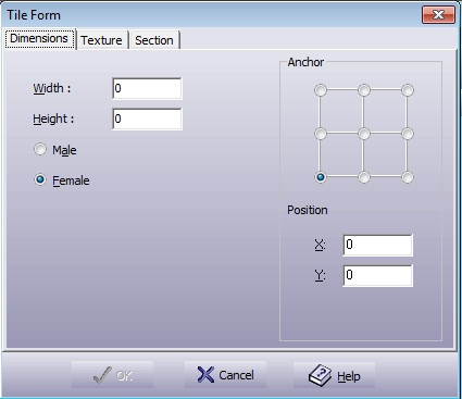
Figure 5.52. Tile Design Texture Dialogue

Tile design texture dialogue

Z Max Selects the surface maximum Z height.
Z Min Selects the surface minimum Z height.
Tol Enters the minimal patch size in units or percent. The smaller the value, the smoother the surface created.
Contrast Defines the relation between dark and light. Positive changes produce a wider range of luminance. Negative changes produce a narrower range of luminance.
Brightness Controls the amount of light to which the picture will be exposed.
Ignore Section Ignore the input of the Section tab.
Invert Reverses the grayscale value within its 256 shades.
Apply Reverses the grayscale value within its 256 shades.
Open Open a raster file for the shade analysis.
Clear Clear the current raster file and changes.

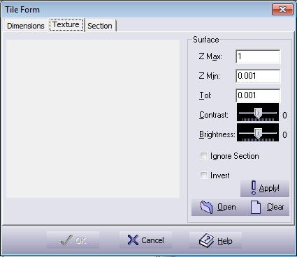
Figure 5.53. Tile Design Section Dialogue
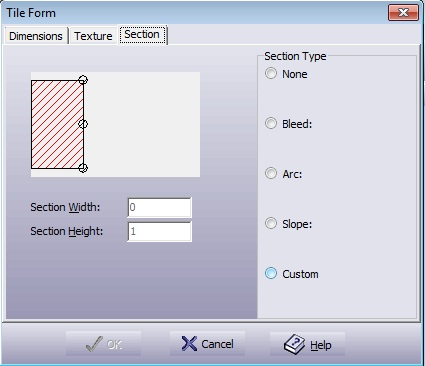
Tile design section dialogue

Section Width The section width.
Section Height The section height.
None No section.
Bleed A section with radius that blends into texture. Define the radius and height.
Arc Arc shaped section.
Slope Slope shaped section.
Custom Create a custom section.

Press OK to create the surface.