| System Menu | ||
|---|---|---|
 |
Chapter 5. Mill |  |
| System Menu | ||
|---|---|---|
| |
Chapter 5. Mill | |
Figure 5.79. System Menu
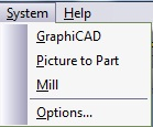
The System Menu enables you to work in different modules of the system simultaneously. The corresponding module button on the toolbar may be pressed to switch to that module.
Figure 5.80. form, Command tab

![[Note]](../images/note.png) |
Note |
|---|---|
|
The toolbars themselves can be modified at all times. To change their position or shape within the module, simply drag or resize them according to your needs. Moving and resizing the toolbars does not require the use of the Customize Toolbar command. This command is only needed when you wish to modify the actual buttons on the toolbars. |
 |
Select from the menu to change the system defaults and parameters, and also to define the measuring method for your job. The Options parameters are set in the System Options dialog box. |
Figure 5.82. Mill form
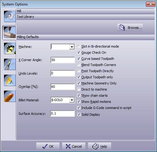
| Default Tool Library | Select the Tool Library file (*.ctr) to use in your job. |
| Machine | Select the default post processor file to create your G-Code files. |
| X Corner Angle | For the Skeleton option, define the maximum angle on which the skeleton algorithm will commit calculations. |
| Undo Levels | Define the number of Undo Levels. |
| Overlap [%] | Enter (in percent) the default value for the Overlap parameter in the Machining Parameters dialog box. |
| Billet Material | Define the material with which you want your billet to appear. |
| Helical Z entry | Default value for Helical Z entry. |
| Surface accuracy | Default value for the model while calculating Equale Z strategy. |
| Slot in Bi-directional mode | Select this option in order to turn on the Bi-directional check box in the Slot window. This will cause the system to create a 2-directional slot toolpath. |
| Gouge Check On | If On, then the toolpath is calculated with the compensation of the tool's shape. If Off, then the toolpath calculations are with respect to the tool tip. |
| Curve based Toolpath |
Use this option to create a smoother toolpath. Figure 5.83. Curve Based Toolpath Example 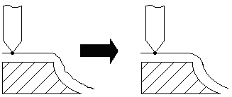
|
| Blend Toolpath Corners |
Select this option to use the preferable spiral toolpath creation. Unselecting this option will perform a regular spiral toolpath with cross points: Figure 5.84. Blend Toolpath Unmarked Example 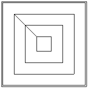 Select this option to get a blend corners spiral toolpath: Figure 5.85. Blend Toolpath Example 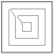
|
| Post Toolpath Directly | Send toolpath calculations directly to the post processor without displaying them on the screen. This option is useful for large jobs, when you do not want to lose time displaying the toolpath but you want the program to create the G-Code directly for machining. |
| Output Toolpath only | Send only toolpath geometries to the post processor in order to create a G-Code. |
| Machine Geometry only | Send only toolpath geometries to the post processor in order to create a G-Code. |
| Direct to Machine | Send the created G-Code directly to the machine. |
| Show chains start | Show start of a chain as a triangle on screen, On/ Off. |
| Show Rapid motions | Default for the → command. |
| Include G code command in script | Sets if the script will include the G code commands. |
| Solid Display | Mark for solid surface display, unmark for transparency. |
Figure 5.86. form
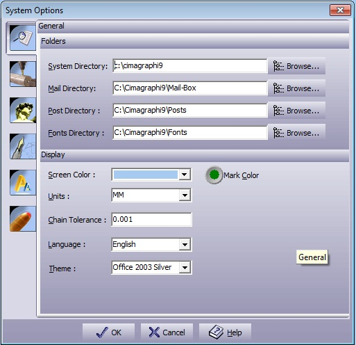
| System Directory | Defines the location of all the system files. This includes the executable files, DLL's, libraries, help files, and utility files. To change this directory, use the button on the right and point to a new directory. |
| Mail Directory | Defines the location of all the temporary files, including the private clipboard files, backup files and temporary files. To change this directory, use the button on the right and point to a new directory. |
| Posts Directory | Defines the location of all the machine drivers. This includes the provided post-processors. To change this directory, use the button on the right and point to a new directory. |
| Fonts Directory | Defines the location of all the fonts provided with the system. The system will automatically detect the Microsoft Windows™-provided True-Type fonts or any other True-Type font properly installed in Windows™. To change this directory, use the button on the right and point to a new directory. |
| Screen Color | Select the preferred background color. |
| Units | Set the work-mode units (mm or inch). |
| Language | Select the language of the system. |
| Chain Tolerance | Define the system wide size for chaining. This value defines the smallest gap to be automatically closed by the system. |
| Show Scales | Define which scales to view by checking the scales you need. |
| Advanced Dialog | When marked, all forms will open in advanced mode. |
| |
 |
|
| Machine Menu |  |
Help Menu |