Setup Menu

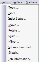
Figure 5.17. Setup Menu

Setup menu

SetupTools

Tools

Opens the Tool Library dialog box, and define the tools to be used in the machining process. An engraving tool may have a conical cross section with a nose tip radius and a corner radius. Many kinds of shaped or tapered engraving tools can be defined including flat, ball, and tapered tools.

Figure 5.18. Setup Tools Dialogue

Setup tools dialogue

Name box Produces a description of the tool automatically based on the values that you define and the kind of tool that you choose. You can also enter your own tool's name.
Height This is the tool's cutting area height. This size represents the maximum cutting depth of the tool.
Side Angle This is half the tool's included angle (in degrees). An angle should be no less than 0° or greater than 90°.
Corner Radius This parameter defines the blending radius between the nose tip plane and the taper angle. The radius is expressed in units and should not exceed the tool's nose radius.
Diameter This is the tool's tip diameter expressed in units. A value of zero leads to a pointed tool.
Flutes This value defines the number of flutes in the cutting tool. This value is limited to a maximum of nine.
Clear magazine
Unload all the tools from the magazine.
Delete tool
Remove a tool from the magazine list. Pick the tool (blue background on the selected tool's name).
Load tool
Load the selected tool from the magazine. The new tool's name (the one in the window will be added to the tool list.
Magazine Setup Displays all tool names and serial numbers in the present magazine. You can load or unload tools from the magazine using the options below. The position corresponds to the position of the machine turret.
Save
Any edited magazine can be saved to a file. Press this button to save a magazine to disk. The extension of the tool library file is CTR.
Open
Load a new tool file. An Open File dialog box appears. Select a file by highlighting the name with the mouse and pressing OK. Navigation in the disk directory tree is also possible from this point.
Types A set of twelve icons enables you to choose the kind of tool that you wish to work with (i.e. Bore, Drill, Sink, Ream, etc.). Press the icon and the definition windows will change according to the selected tool.
Tool Library The library keeps a record of all defined tools. Select the (+) and (-) buttons to add and delete tools from the library.

SetupBillet

Billet

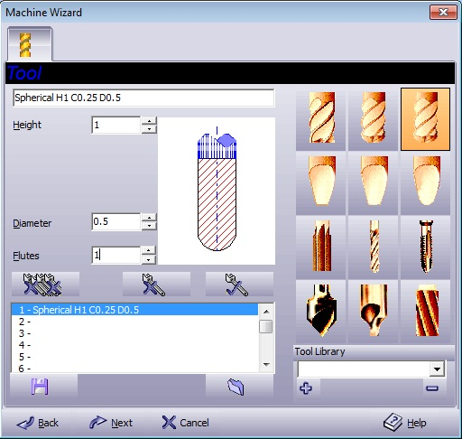
To define the Billet's material, dimensions and location, select Billet from the Setup menu. The following dialog box displays the part you select for the job:

Figure 5.19. Setup Cube Billet Dialogue

Setup cube billet dialogue

Billet Dimensions

Width X Billet width. The default is 3% to 5% bigger then the marked groups that exist on the layout.
Depth Y Billet depth. The default is 3% to 5% bigger then the marked groups that exist on the layout.
Height Z Define the billet thickness. The default is 25 units unless 3D geometry or surface exist on the layout. In this case the billet thickness is the minimum that includes the Z changes in this toolpath.

Position Define the billet position, X,Y,Z according to the anchor box.
Default machine plane

Top
Billet top
Stay on billet top plane.
Bottom
Billet bottom
Machine to the bottom of the billet.

Material Displays the name of the material to be used. You can change the billet material by opening the Material Ruler and selecting from the list, or you can open the Material Library dialog box by clicking on the material toolbar icon and entering a new material name. The name will then be added to the Material Ruler. Billet material is useful in the simulation display, where the rendering is imitating the selected material.
Pick
Takes minimum and maximum parameters, and creates a billet large enough to contain all the surfaces.
Anchor box Reference point for the Position values.

Figure 5.20. Setup Ring Billet Dialogue

Setup ring billet dialogue

Dimensions

Diameter Inner diameter.
Outer Diam Outer diameter.
Margin stop

Additional stock for the ring billet.

Example.  If you need to cut the ring under the diameter hight, you need to add a negative value.

Axis Length Length of the billet.

Axis Position

X,Y,Z Axis start point.
Along X Along X axis.
Along Y Along Y axis.

Material Displays the name of the material to be used. You can change the billet material by opening the Material Ruler and selecting from the list, or you can open the Material Library dialog box by clicking on the material toolbar icon and entering a new material name. The name will then be added to the Material Ruler. Billet material is useful in the simulation display, where the rendering is imitating the selected material.

Figure 5.21. Setup Elliptic Billet Dialogue

Setup elliptic billet dialogue

Billet Dimensions

Width X Billet width. The default is 3% to 5% bigger then the marked groups that exist on the layout.
Depth Y Billet depth. The default is 3% to 5% bigger then the marked groups that exist on the layout.
Height Z Define the billet thickness. The default is 25 units unless 3D geometry or surface exist on the layout. In this case the billet thickness is the minimum that includes the Z changes in this toolpath.

Position Define the billet position, X,Y,Z.
Default machine plane

Top Stay on billet top plane.
Bottom Machine to the bottom of the billet.

Material Displays the name of the material to be used. You can change the billet material by opening the Material Ruler and selecting from the list, or you can open the Material Library dialog box by clicking on the material toolbar icon and entering a new material name. The name will then be added to the Material Ruler. Billet material is useful in the simulation display, where the rendering is imitating the selected material.
Pick
Takes minimum and maximum parameters, and creates a billet large enough to contain all the surfaces.
Anchor box Reference point for the Position values.

Figure 5.22. Setup Custom Billet Dialogue

Setup custom billet dialogue

Billet Dimensions

Height Z Define the billet thickness. The default is 25 units unless 3D geometry or surface exist on the layout. In this case the billet thickness is the minimum that includes the Z changes in this toolpath.

Pick geometry from work area Presents all layers that contains one closed chain. Select the chain to describe the billet shape.
Default machine plane

Top Stay on billet top plane.
Bottom Machine to the bottom of the billet.

Material Displays the name of the material to be used. You can change the billet material by opening the Material Ruler and selecting from the list, or you can open the Material Library dialog box by clicking on the material toolbar icon and entering a new material name. The name will then be added to the Material Ruler. Billet material is useful in the simulation display, where the rendering is imitating the selected material.


SetupMove

Move

Change the physical location of any marked group and surface. The following dialog box appears in which you define the Move parameters:

Absolute

Figure 5.24. Setup Move Relative Dialogue

Setup move relative dialogue

Enter the By X,By Y and By Z parameters to define the offset of the group's center from the chosen point.

Absolute

Figure 5.25. Setup Move Absolute Dialogue

Setup move absolute dialogue

Enter the X, Y and Z parameters to define the offset of the group's center from the chosen point. Select the group's movement point by selecting a point relative to the frame. This is defined by one of twenty seven radio buttons: there are nine buttons on each of the three levels.

Point At
Point at

Click Point At to exit the dialog box and use the mouse to determine the insertion point. A Cursor Pick Type toolbar appears enabling you to select the method of your manual clicking. For a description of the Cursor Pick Type options see the intro chapter.

Figure 5.26. Cursor Type Dialogue

Cursor type dialogue

Polar

Figure 5.27. Setup Move Polar Dialogue

Setup move polar dialogue

Type the Distance and At Angle that the groups are to move.

Press OK to confirm the changes in definition and setup. Press Cancel to exit without changes. Press Help to open the On-line Help.

SetupRotate

Rotate

Select Rotate from the Setup menu to change the orientation angle of a marked geometry group or surface.

Figure 5.28. Setup Rotate Dialogue
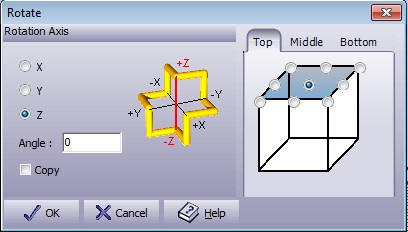
Setup rotate dialogue

X,Y,Z Select on which axis the group is to rotate. The selected axis is highlighted with a red line on the representative image.
Angle Select the angle by which the rotation is to occur.
Anchor Select the group's rotational point by selecting a point relative to the frame. This is defined by one of twenty seven radio buttons: there are nine buttons on each of the three levels.

Press OK to confirm the changes in definition and setup. Press Cancel to exit without changes. Press Help to open the On-line Help.

SetupScale

Scale

Use the Scale option to change the scale size of a marked group or surface. Mark the group to be scaled and select Scale from the Setup menu. Scale the items manually, by height, width, or percent.

Figure 5.29. Setup Scale Dialogue
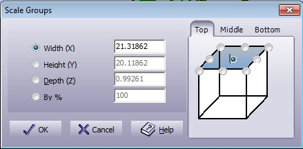
Setup scale dialogue

Width The marked group will be scaled to fit the width you selected. The height and depth are adjusted accordingly. Select Width and enter the new width in the entry box.
Height The marked group will be scaled to fit the height you selected. The width and depth are adjusted accordingly. Select Height and enter the new height in the entry box.
Depth The marked group will be scaled to fit the depth you selected. The width and height are adjusted accordingly. Select Depth and enter the new depth in the entry box.
By % Enter scale factor in percents. 100% is equal to scale factor 1.0 (no change), 200% is double scale, etc.
Anchor Select the group's fixed point by selecting a point relative to the frame. This is defined by one of twenty seven radio buttons: there are nine buttons on each of the three levels.

Press OK to confirm the changes in definition and setup. Press Cancel to exit without changes. Press Help to open the On-line Help.

SetupMirror

Mirror

Select Mirror from the Setup menu to create a mirror image of the marked group or surface. This function is particularly useful for engraving forms for molding.

Figure 5.30. Setup Mirror Dialogue

Setup mirror dialogue

Mirror Plane

XY Reflect the marked group over the XY-axis.
XZ Reflect the marked group over the XZ-axis.
YZ Reflect the marked group over the YZ-axis.

Anchor Select the group's reference point by selecting a point relative to the frame. This is defined by one of twenty seven radio buttons: there are nine buttons on each of the three levels.

Press OK to confirm the changes in definition and setup. Press Cancel to exit without changes. Press Help to open the On-line Help.

SetupSet Machine Start

Set machine start

Specify the location of the chain's new start point. The user thus controls the first point from which the machining process starts. In this mode, the user must click on a new start point for the chain. The command is available only for geometries. The start point of a toolpath depends on the start point of the geometry from which it originates. For open contours, the system will select the nearest edge as the start point. This function is in toggle mode. Select a new command from the menu to cancel this mode.

SetupSketch

Sketch icon

This function enables quick sketching of a new geometry. It can be used to define an outline or to create a base for manual slotting. Use the Cursor Type dialog box to define the exact cursor position then point and click to create entities.

Figure 5.31. Sketch Dialogue

Sketch dialogue

Figure 5.32. Cursor Type Dialogue
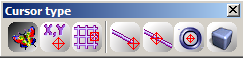
Cursor type dialogue

Arc

To draw arcs, select the Arc radio button. An arc requires:

One click to define an arc that is tangent to a previously sketched entity.

Two clicks: one for the arc end-point and the second for defining the circumference. This option is active in corner sketching mode.

Three clicks: first arc on a sketching chain requires start-point, the second for end-point and the third for defining the circumference.

Line

To draw lines, select the Line radio button. A line requires one click: for the line end-point (except from the first line on a sketching chain that requires two points for start-point and end-point).

Curve

Draws a spline curve.

Corner

The default is Corner sketching, which means that sharp corners will connect two neighboring entities:

Corner example

Tangent

To create smoother chains, select Tangent. Each entity that comes after an arc or is an arc itself, will be displayed as tangent to the previous entity:

Tangent example

Snap 5

Forces diagonal lines to set to the nearest 5° line. This is useful when sketching over geometry that involves parallel lines. The sketched lines will be parallel even with non-accurate digitations. Arcs are affected by their end angle to match the 5° roundup.

New icon New Shape Start a new chain on the next click position, disconnected from the previous one.
Loop icon Loop

Automatically connect the edges of the last sketched chain in a straight line to form a closed contour.

Loop example

SetupJob Information

Job information

Select Job Information from the Setup menu to open the Job Information dialog box and view the list of actions and definitions that applied to the job. You can also add remarks and send the job information report to print. The job information report presents four subjects about your job:

  • Billet - definitions and remarks.

  • Tools - defined for the job.

  • Groups - used in the job (including toolpaths).

  • Remarks - those remarks that were added.

Figure 5.33. Setup Job Information Dialogue
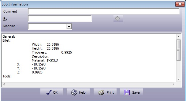
Setup job information dialogue

Use the Comment and By input windows to create the remarks you want to add to the report, and press the + button to execute. Select the Machine you are using to get the approximate time for completing your job. The remark that you enter will be followed by the date and time of addition. The Job Information report is updated each time one of the parts change.