Transform Menu

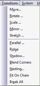
Figure 3.66. Transform Menu

Transform menu

Abstract

The transformations are set of operators that are performed over marked entities. If no entity is marked, the Transform menu items will be grayed. Below is a very brief summary of the Transform Menu options.

  • Move: Move or copy the marked entities.

  • Rotate: Move or copy around virtual circle center.

  • Scale: Change entities size.

  • Mirror: Invert the marked entities as reflected to horizontal/vertical or diagonal line.

  • Stretch: Distort the marked entities in manual.

  • Parallel: Create an offset to marked chains.

  • Ridge: Convert single-line chains to double-line closed contours.

  • Shadow: Apply shadow effects.

  • Blend Corners: Convert all sharp corners to rounded ones.

  • Nesting: Compress marked closed contours to save layout size.

  • Fit on Chain: Place entities along a chain.

  • Break All: Disconnects marked intersecting entities.

TransformMove

Move

Move or copy objects to a new location. The anchor point defines the reference point on the object or group. An anchor may be selected by one of the following nine (9) points around the object: the four corners, the four mid-edges, and the center. The default is the anchor on the screen.

Figure 3.67. Transform Move Absolute Dialogue
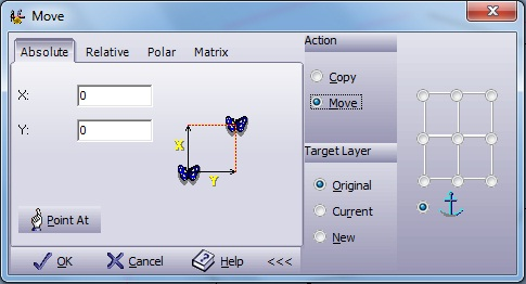
Transform move absolute dialogue

The Advanced Mode Button Advanced mode button is found on the bottom right of the screen. The button is a toggle operation, which opens and closes the Advanced Features section.

Figure 3.68. Transform Move Absolute Advanced Dialogue

Transform move absolute advanced dialogue

The Advanced Feature Section appears in all four modes (Absolute, Relative, Polar and Matrix) and contains the following options:

Action

Choose the transformation method:

Copy - Create a new entity like the one selected and translate it. (This is the default setting).

Move - Translate the selected entity without duplicating it.

Target Layer

Choose the transformation method:

Original - Leave the entity in its original layer. (This is the default setting).

Current - Copy or move the entity to the current active layer.

New - Create a new layer and pass the translated entity to it.

Reference point Select the location of the reference point relative to the frame. This is defined either by one of the nine radio buttons or by the default anchor position.
Absolute Mode:
Target Point Enter the absolute location of the reference point on the job's screen. You can select the absolute point by entering the coordinate values in the X, Y edit boxes, or press Point At to highlight the chosen point on the screen.

Figure 3.69. Transform Move Relative Dialogue

Transform move relative dialogue

by X Enter the space between two neighboring copies of the selected entities in the X direction.
by Y Enter the space between two neighboring copies of the selected entities in the Y direction.
Copies Enter the desired number of copies.

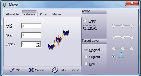
Figure 3.70. Transform Move Polar Dialogue

Transform move polar dialogue

Distance Enter the distance value between two neighboring copies.
At Angle Enter the vector's angle between two neighboring copies.
Copies Enter the desired number of copies.

Figure 3.71. Transform Move Matrix Dialogue

Transform move matrix dialogue

by X Enter the space between two neighboring copies of the selected entities in the X direction.
by Y Enter the space between two neighboring copies of the selected entities in the Y direction.
Copies X Select the number of copies in the X direction.
Copies Y Select the number of copies in the Y direction.

TransformRotate

Rotate

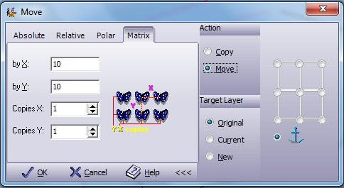
Change the angle of an element or group.

Figure 3.72. Transform Rotate Angle Dialogue

Transform roate angle dialogue

The Advanced Mode Button Advanced mode button is found on the bottom right of the screen. The button is a toggle operation, which opens and closes the Advanced Features section.

Figure 3.73. Transform Rotate Angle Advanced Dialogue

Transform rotate angle advanced dialogue

The Reference Point Section is in all three modes (Angle, Full Circle and Matrix) and contains the following options:

Transform

Choose the transformation method:

Copy - Create a new entity like the one selected and translate it. (This is the default setting).

Move - Translate the selected entity without duplicating it.

Target Layer

Choose the transformation method:

Original - Leave the entity in its original layer. (This is the default setting).

Current - Copy or move the entity to the current active layer.

New - Create a new layer and pass the translated entity to it.

Rotate Individuals

Figure 3.74. Rotate Individuals Marked Example

Transform rotate rotate individuals marked example

Marked - Marked entities are also rotated around their center with the same angle of the rotation around the reference point.

Figure 3.75. Rotate Individuals Un Marked Example

Transform rotate rotate individuals marked example

Un Marked - Marked entities rotate only around the reference point and not around their center.

Reference point Select the location of the reference point relative to the frame. This is defined either by one of the nine radio buttons or by the default anchor position.
Angle Mode:
Delta Angle Rotate the selected entities relative to the current vector orientation (the vector connecting the reference point to the rotation point). Enter the angle of rotation in degrees.
Absolute Angle Rotate the selected entities absolute to the horizon line. Enter the angle of rotation in degrees.
# Copies Enter the number of copies you wish to make from the selected entities.
Rotation Center

Enter the absolute location of the Rotation Center point.

You can select the absolute point by entering the coordinate's values in the X, Y edit boxes, or by pressing Point At to the place on the screen for the chosen point.

Figure 3.76. Transform Rotate Full Circle Dialogue

Transform rotate full circle dialogue

Copies Select the number of copies you wish to create from the original entities. For example, "4" will perform four copies with a 90° angle between each neighboring copy in the defined circle.
Override Original Items This option is available only if you select to move the transformed entities to a new layer. Select this option if you allow the copies to overlap the original entities.
Rotation Center

Enter the absolute location of the Rotation Center point.

You can select the absolute point by entering the coordinate's values in the X, Y edit boxes, or by pressing Point At to the place on the screen for the chosen point.

Figure 3.77. Transform Rotate Matrix Dialogue

Transform rotate matrix dialogue

L Enter the length between two neighboring copies.
A Enter the vector angle between two neighboring copies.
Copies L Select the number of copies in a line.
Copies A Select the number of rotations.
Scale Each

Scale each copy created. The scale value is calculated from the ratio between the distances of the copy to the center of rotation, to the distance between the original to the center of rotation.

Figure 3.78. Scale Each Example

Scale each example

Rotation Center

Enter the absolute location of the Rotation Center point.

You can select the absolute point by entering the coordinate's values in the X, Y edit boxes, or by pressing Point At to the place on the screen for the chosen point.

TransformScale

Scale

Change the scale size of an object. Mark the element or group of elements to be scaled and select Scale from the Transform menu. The Scale dialog box appears and displays the current dimensions of the object. You can scale the object manually, by height, width, or by percentage.

Figure 3.79. Transform Scale Single Scale Dialogue

Transform scale single scale dialogue

The Advanced Mode Button Advanced mode button is found on the bottom right of the screen. The button is a toggle operation, which opens and closes the Advanced Features section.

Figure 3.80. Transform Scale Single Scale Advanced Dialogue

Transform scale single scale advanced dialogue

The Reference Point Section is both modes (Single Scale and Multiple Scale) and contains the following options:

Transform

Choose the transformation method:

Copy - Create a new entity like the one selected and translate it. (This is the default setting).

Move - Translate the selected entity without duplicating it.

Target Layer

Choose the transformation method:

Original - Leave the entity in its original layer. (This is the default setting).

Current - Copy or move the entity to the current active layer.

New - Create a new layer and pass the translated entity to it.

Reference point Select the location of the reference point relative to the frame. This is defined either by one of the nine radio buttons or by the default anchor position.
Single Scale:
by Height The marked group will be scaled to fit the height you enter in units. The width is adjusted accordingly. Select by Height and enter the new height in the textbox.
by Width The marked group will be scaled to fit the width you enter. The height is adjusted accordingly. Select by Width and enter the new width in the text box.
by Percents Select by Percent and enter the percentage scale factor in the text box. 100% is equal to scale factor 1.0 (no change), 200% is double scale, etc.

Figure 3.81. Transform Scale Multiple Scale Dialogue

Transform scale multiple scale dialogue

Final Height Select this option to scale the selected entities to a specified height and enter this height in the edit window.
Final Width Select this option to scale the selected entities to a specified width and enter this width in the edit window.
Final Percent Select this option to scale the selected entities to a specified percent and enter this percentage in the edit window.
# Stages

Enter the number of stages in which you wish to perform the scaling. For example, if you started with a height of 1 and chose a final height of 11 and then selected 4 stages, 4 copies will be displayed, with each copy increasing in size by 2.5 units.

Figure 3.82. Transform Scale Multiple Scale Example

Transform scale multiple scale example

TransformMirror

Mirror

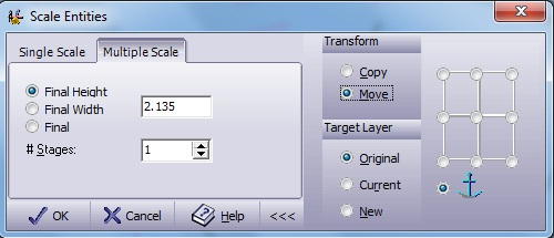
To reflect an object over an axis of symmetry, select the Mirror function in the Transform menu. The following dialog box appears:

Figure 3.83. Transform Mirror Dialogue

Transform mirror dialogue

The Advanced Mode Button Advanced mode button is found on the bottom right of the screen. The button is a toggle operation, which opens and closes the Advanced Features section.

Figure 3.84. Transform Mirror Advanced Dialogue

Transform mirror advanced dialogue

Transform

Choose the transformation method:

Copy - Create a new entity like the one selected and translate it. (This is the default setting).

Move - Translate the selected entity without duplicating it.

Target Layer

Choose the transformation method:

Original - Leave the entity in its original layer. (This is the default setting).

Current - Copy or move the entity to the current active layer.

New - Create a new layer and pass the translated entity to it.

Reference point Select the location of the reference point relative to the frame. This is defined either by one of the nine radio buttons or by the default anchor position.
Horizontal Creates a reflection on the Y-axis.
Vertical Creates a reflection on the X-axis.
Point Freely Enables you to place a mirror line where the image is reflected. Select Point Freely and select two points for the reflection line. The cursor changes from a one-click to a two-click cursor. When the second spot is selected the image is automatically reflected.

TransformStretch

Stretch

Enables you to place boundaries consisting of lines and arcs around a marked group in order to change and move them. You can modify the shape of the boundary, and the shape of the group will be transformed to fit the geometry of the new boundary. A new (stretched) group appears beside the old (basic) group. Select Stretch from the Transform menu. The Stretch Parameters dialog box appears:

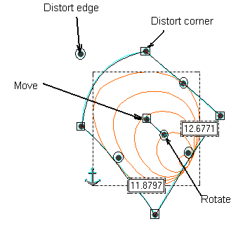
Figure 3.85. Transform Stretch Box Dialogue

Transform stretch box dialogue

The Stretch Box

The Stretch Box is a closed set of lines and arcs that bound marked elements. Ten control points are displayed in this box.

  • The circle in the center is used for moving the whole group. Select the center circle and drag it to a new location. Use the circle in the four corners of the Stretch Box to stretch the corners. Drag a corner with the mouse and then release the mouse button.

  • Use the small circle at the center of each boundary line or arc to move the boundary.

  • Moving the center circle will relocate the marked entities without distorting them.

  • Moving the small circle that is connected to the center square will rotate the marked entities without distorting them.

The ten control points can be limited to a certain motion according to the motion control switches in the Stretch Parameters dialog box. Use Esc to exit the function.

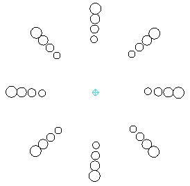
Figure 3.86. Stretch Points Example

Stretch points example

Pre-Defined Options

To define the shape of the default stretch box, select one of the six options in the upper part of the main Stretch Parameters dialog box. Enter the necessary parameters for each selection when prompted. Note that the stretch box may later be altered freely and that the pre-defined options may also be used as a starting point only.

Manipulating the Stretch

The right part of the main Stretch Parameters dialog box controls the way in which the stretch box will behave. The pre-defined options set the Stretch Box to a starting point. If you wish to manipulate the Stretch Box manually, the following options are provided in the right part of this window:

Center X This is the X coordinate of the center of the default stretch box (i.e. the center rectangle).
Center Y This is the Y coordinate of the center of the default stretch box (i.e. the center rectangle).
Rotation The entire stretch box can be rotated around the center point at a given angle.
Arcs XY By moving the control points, all sides of the Stretch Box turn into arcs. This is the system default.
Arcs X Arcs can be created only in the horizontal direction. In the vertical motion, the center control point will move the element up or down but will not form an arc.
Arcs Y Arcs can be created only in the vertical direction. In the horizontal motion, the center control point will move the element left or right but will not form an arc.
Lines This option disables all arc bounding possibilities. It is used to create a linear or angular stretch.
Free This indicates no limitations in the way the Stretch Box can move. When using this control mode, each control point moves independently of any other control point. This is the system default.
Follow Moving a control point on one side causes the control point on the opposite side to move in the same direction. For example, if you move the upper right control point up and to the right, the upper left control point will move the same distance in X and the lower right control point will move the same distance in Y. The middle edge points can be moved freely.
Mirror Moving a control point on one side will cause the control point on the opposite side to move in the opposite direction. For example, if you move the upper right control point up and to the right, the upper left control point will move in the opposite direction, and so will the lower right control point.

Box (Rectangle) Stretch

Select Box to define the height and width of a rectangular Stretch Box. The default values are the current Height and Width of the marked elements. This option creates a stretch rectangle with the new dimensions.

Figure 3.87. Transform Stretch Box Dialogue

Transform stretch box dialogue

Circle Stretch

Select Circle to enter the Radius for a Circle Stretch. The resulting Stretch Box appears as a circle, and activating the stretch will give the effect similar to that of a fish-eye camera lens.

Figure 3.88. Transform Stretch Circle Dialogue

Transform stretch circle dialogue

Section Stretch

This option is useful for text that has to be set on an arc and distorted to be wider at the outer radius than at the inner radius. Select Section to define a Section Stretch. Enter the external Radius and the delta radius H of the section, the Start Angle and the End Angle. H is the difference between the outer radius and the inner radius. Mirror images by entering an end angle that is smaller than the start angle.

Figure 3.89. Transform Stretch Section Dialogue

Transform stretch section dialogue

Skew Stretch

Slant the image sideways. When prompted, enter the height and width of the new group and the slant angle.

Figure 3.90. Transform Stretch Skew Dialogue

Transform stretch skew dialogue

Trapeze Stretch

Select Trapeze to give the stretch image a trapezoidal shape. When prompted, enter the width, height, and Angle of the trapezoid.

Figure 3.91. Transform Stretch Trapeze Dialogue

Transform stretch trapeze dialogue

Banner Stretch

Give the stretch box a banner look. When prompted, enter the banner width. Different left - H2 and right - H1 heights can be entered.

[Note] Note

D1 and D2 can be negative or positive.

Figure 3.92. Transform Stretch Banner Dialogue

Transform stretch banner dialogue

TransformParallel

Parallel

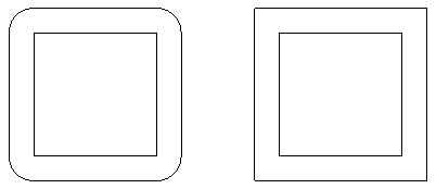
The Parallel feature is a unique function that enables you to create an offset image next to a selected image. The effect creates a double line on lines and curves. Concentric circles are created for circles, and a frame effect is created for rectangles. To define the Parallel parameters, select Parallel from the Transform menu.

Figure 3.93. Transform Parallel Dialogue
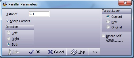
Transform parallel dialogue

The Advanced Mode Button Advanced mode button is found on the bottom right of the screen. The button is a toggle operation, which opens and closes the Advanced Features section.

Figure 3.94. Transform Parallel Advanced Dialogue

Transform Parallel advanced dialogue

Target Layer

Choose the transformation method:

Original - Leave the entity in its original layer. (This is the default setting).

Current - Copy or move the entity to the current active layer.

New - Create a new layer and pass the translated entity to it.

Ignore Self Cross

This parameter sets the parallel contour type: for some applications, such as ruled surfaces in the Mill and Picture to Part modules. The offset of an image may appear confused and random, due to self-crossing and loops. Unselecting Ignore Self Cross overrides this problem, as it operates as a tool path calculating.

Figure 3.95. Transform Parallel Ignore Self Cross

Ignore Self Cross

Original Image -> Ignore Self Cross Marked -> Ignore Self Cross Un Marked

Distance The distance (in units) between the offset group and the marked group. This is the space between the double lines. In the text box, enter the offset.
Sharp Corners

Select this option for creating Sharp Corners after offsetting the entities. If you do not select this option, arc edges are created.

Figure 3.96. Transform Parallel Sharp Corners

Sharp corners

Without Sharp Corners -> With Sharp Corners

Direction

This parameter determines which side of the original line the offset is drawn. Choose Left, Right, or Both.

Parallel is affected in the direction specified by the arrows of the marked group. The following figures detail the Parallel feature:

Right

Figure 3.97. Transform Parallel Right

Right

Left

Figure 3.98. Transform Parallel Left

Left

Press OK to make changes. To exit without changes, press Cancel. Press Side to select manually on which side to create a parallel. The button is enabled only if Left or Right option is selected.

TransformRidge

Ridge

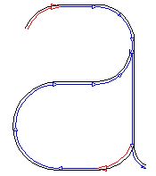
Replace a single line contour with a closed contour with the width and shape specified in the GraphiCAD tab of the SystemOptions. Default width of 0.01 units and round shape. The function will automatically offset and trim all the chained elements.

Figure 3.99. Transform Ridge Example

Transform ridge example

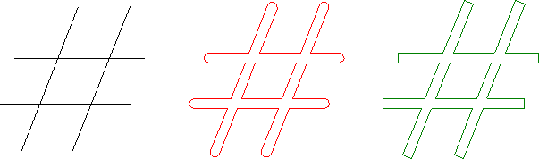
Original countor -> Ridge, Sharp Corners Un Marked -> Ridge, Sharp Corners Marked

This function is extremely important when a stamp has to be made out of single line characters or other geometries. After the ridge is performed, an offset (parallel) or milling offset contour is achievable.

TransformShadow

Shadow

Powerful function that adds a drop shadow behind or in front of the shape. This results in a 3D effect on the shape. A shadow can be attached to any of the drawn shapes in Ground or Wall projection. Select Shadow from the Transform menu to set Shadow parameters:

Figure 3.100. Transform Shadow Dialogue

Transform Shadow Dialogue

Ground Ground shadow

This six-point grid defines the direction of the shadow projecting on the shape.

Figure 3.101. Transform Shadow Ground Example

Transform shadow ground example

Wall Wall shadow

This eight-point grid defines the direction of the shadow projecting on the shape.

Figure 3.102. Transform Shadow Wall Example

Transform shadow wall example

Offset

In Ground shadow: the distance (in units) between the shadow baseline and the marked shape baseline.

In Wall shadow: the distance (in units) between the original image and its shadow.

Length The length (in units) of the shadow group. This function controls the distortion of the ground projection shadow. Length is not active for the Wall projection.

The shadows will always be created on a new layer.

Press OK to apply the changes. Press Cancel to exit without changes.

TransformBlend Corners

Blend Corners

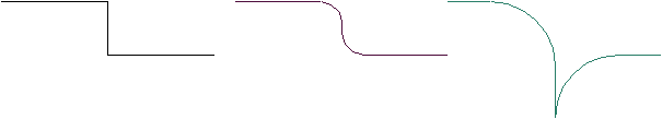
Changes all the sharp corners along marked chain of entities to round corners in a constant radius.

Figure 3.103. Transform Blend Corners Example

Transform blend corners example

[Note] Note

It is your responsibility to check that the blending radius is small enough to be assigned to the chain entities. Otherwise, the results may be unpredictable.

Figure 3.104. Transform Blend Corners Note!

Transform blend corners note!

Original Contour -> Blending is OK -> Radius is too big

TransformNesting

Nesting

Arranging the job parts in the optimal way in order to minimize material waste. Before operating this function, mark the geometries to be arranged and those that represent the billet shape and dimensions.

Figure 3.105. Transform Nesting Dialogue

Transform nesting dialogue

Limits

No bounds

Compress all marked groups to occupy the smallest area.

Figure 3.106. Nesting No Bounds Example

Nesting no bounds example

"Layer name"

Compress all marked groups inside largest contour in the in specified layer.

Figure 3.107. Nesting "Layer Name" Example

Nesting "layer name" example

Flip & Angles

No flip
Disable geometry flip (mirroring).
Flip
Enabled geometry flip (mirroring).
Angle by Boundary Angle step is determined by the specific boundary angle.
No rotation
No rotation allowed.
180° rotation
Only 180° rotation allowed.
90° step rotation
Only 90° step rotation allowed.
45° step rotation
Only 45° step rotation allowed.
5° step rotation
5° step rotation allowed.

Spacing

Minimum The minimal distance between two neighboring groups.
Make average Space the groups evenly in order to get a better fit.

Repetitions

Repeat nesting Mark two groups and the system will nest as many as possible of the small one within the larger one
Limit to Limit the number of small groups to be nested using Repeat nesting.

TransformFit on Chain

Fit on chain

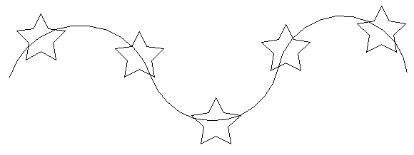
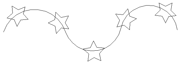
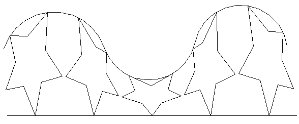
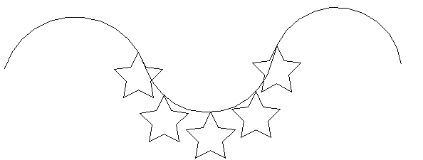
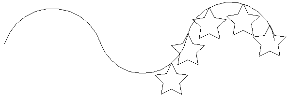
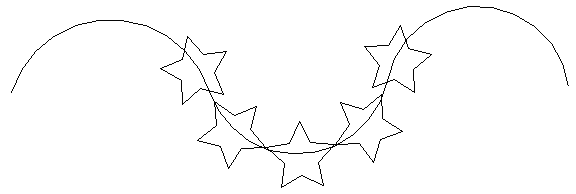
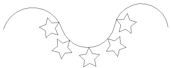
Enables you to fit marked geometric entities onto a selected chain. Mark the element or group of elements to be transformed and either click on the Fit on Chain icon, or, select Fit on Chain from the Transform menu. The Fit Marked on Chain dialog box appears with a default of the previously selected options. Chose your options from the dialog box and click Select; the dialog box disappears and the work area reappears. With the cursor click on the chain you want the entities to be placed on.

Figure 3.108. Transform Fit on Chain Dialogue

Transform fit on chain dialogue

Scatter Mode

These four options enable you to select how the entity will be appearing along or between selected chains. Below are illustrations of the four Scatter Mode options. The default for Chain Alignment is Fit; the default for Symbol Position is Center.

Pre-Scatter Mode

Figure 3.109. Transform Fit on Chain - "before picture"

Before applying fit on chain

This is how the image would look before any of the Fit on Chain options are selected.

Position On Chain

Figure 3.110. Transform Fit on Chain - Position On Chain

Position on chain

The entities keep their original angle.

Normal To Chain

Figure 3.111. Transform Fit on Chain - Normal To Chain

Normal to chain

The entities follow the angle of the chain.

Normal And Stretched

Figure 3.112. Transform Fit on Chain - Normal And Stretched

Normal and stretched

The entities centerline is always normal to the curve. No collision check is made between sequential characters.

Between Two Chains

Figure 3.113. Transform Fit on Chain - Between Two Chains

Between two chains

The entities are stretched to fit in the space between the two chains.

Chain Alignment

This option enables you to select the area on the entity by which the alignment should be made. Below is an illustration of the five Chain Alignment options. The default for Scatter Mode is Position on Chain; the default for Symbol Position is Bottom.

Left

Figure 3.114. Transform Fit on Chain - Left

Left

The entities are equally aligned to the left of the chain without colliding. The entities keep their original angle.

Right

Figure 3.115. Transform Fit on Chain - Center

Right

The entities are equally aligned to the Center of the chain without colliding. The entities keep their original angle.

Right

Figure 3.116. Transform Fit on Chain - Right

Right

The entities are equally aligned to the Right of the chain without colliding. The entities keep their original angle.

Fit

Figure 3.117. Transform Fit on Chain - Fit

Fit

The entities are equally distributed along the chain. The entities keep their original angle.

None

Figure 3.118. Transform Fit on Chain - None

None

The entities are equally distributed along one chain at manually selected points. The Select button will place all the entities in one area on the chain. The 2 Click button distributes the entities along two selected points.

[Note] Note

The Cursor Pick Type will vary the points of distribution.

Symbol Position

This option enables the marked entity to be aligned onto the chain surface. Below is an illustration of the three Symbol Position options. The default for Scatter Mode is Normal to Chain; the default for Chain Alignment is Center.

Top

Figure 3.119. Transform Fit on Chain - Top

Top

The entities are aligned to the top of the chain. The entities follow the angle of the chain.

Center

Figure 3.120. Transform Fit on Chain - Center

Center

The centers of the entities are aligned on the chain. The entities follow the angle of the chain.

Bottom

Figure 3.121. Transform Fit on Chain - Bottom

Bottom

The entities are aligned to the bottom on the chain. The entities follow the angle of the chain.

Copies Number of copies to align along the chain.

TransformBreak All

Transform Break All

Disconnects all marked intersecting entities. Mark the entities to be disconnected by either clicking on the Break All icon, or, selecting Break All from the Transform menu. The disconnections are only visible by activating the Arrows option. Either click on the Arrow icon, or, select Arrows from the View menu.

The diagrams below illustrate how an image would look;

Figure 3.122. An image with Break All activated.

Break All with no arrows

[Note] Note

There is no evidence from the image that the intersecting entities are disconnected.

Figure 3.123.  An image with ViewArrows activated before activating Break All.

Before Break All with arrows

Figure 3.124.  An image with ViewArrows activated after activating Break All.

After Break All with arrows