View Menu

Figure 3.56. View Menu

View menu

ViewZoom

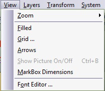
Figure 3.57. View Zoom Sub Menu

View zoom sub menu

ViewZoomAll

Zoom all
Show the entire job. Ctrl-A

ViewZoomDouble

Zoom double
Expand the job by a factor of two. (A roller-mouse can be used for this operation). Ctrl-D

ViewZoomHalf

Zoom half
Reduce the job by a factor of two. (A roller-mouse can be used for this operation). Ctrl-H

ViewZoomWindow

Zoom window
Define a window for new scale. Ctrl-W

ViewZoomPrevious

Zoom previous
Jump to the previous zoom. Ctrl-P

ViewZoomSelected

Zoom selected
Show the selected entities (those who are marked). Ctrl-L

ViewFilled

View filled

Fills close shapes with color. The fill color is the color of the layer holding the shape.

When filled mode is active, a checkmark is displayed beside the menu option and the button remains pressed. To cancel filled mode, repeat the command as a toggle switch.

[Note] Note

Open chains may cause unexpected results. Layers order is also important.

ViewGrid

View grid

Define a grid to be displayed on the screen. Use this grid as a reference when operating on the image. Two grid types are available: rectangular and isometric (triangular). Refer to the grid points by selecting the mouse grid cursor. The grid is displayed by a rectangular net of small user-defined color crosses or by a net of isometric triangles. The grid is a background reference only and cannot be copied to the clipboard.

Figure 3.58. Grid Parameters Dialogue

Grid parameters dialogue

X origin The X-coordinate from which the grid origin is calculated. All the horizontal spaces will be calculated according to this coordinate.
Y origin The Y-coordinate from which the grid origin is calculated. All the vertical spaces will be calculated according to this coordinate.
X spacing The space between the grid columns or isometric triangles.
Y spacing The space between the grid rows (in units).
Show Grid The grid is displayed when this box is checked.
Net Display A net of rectangular grid lines is displayed when this box is checked.
Isometric Grid A grid based on isometric triangles is displayed when this box is checked. The isometric grid can be displayed with or without the net.
Grid Color A combo box to select the grid display color.

Figure 3.59. Grid Display Options

Grid display options

ViewArrows

Arrows icon

Vector directions can be displayed or hidden by turning this option on or off.

ViewShow Picture On/Off

Show picture on/off icon

Loading a raster image file as a background is a very useful tool for both digitizing and for general reference. The background picture can be displayed or hidden by toggling this function. Select Show Picture On/Off from the View menu or press Ctrl-B to toggle between showing the picture and hiding the picture.

ViewMarkbox Dimensions

Markbox dimensions icon

The Markbox dimension of any image or text can be displayed or hidden by either turning this option on or off. You can select or unselect this option by selecting the icon or by selecting Markbox Dimensions from the View menu. To have markbox dimensions continually displayed, select Options from the Systems menu. Select the GraphiCAD ribtab and click on Show Markbox Dimensions.

Figure 3.60. Markbox Dimensions

Markbox dimensions

ViewFont Editor

Font editor icon

Creates new fonts and edits existing fonts. Select Font Editor from the View menu. The Fonts dialog box appears.

Figure 3.61. Fonts Dialogue

Fonts dialogue

Select the font to edit and press OK to open the Font Editor dialog box.

Figure 3.62. Fonts Editor Dialogue

Fonts editor dialogue

Fonts map This map displays all the characters related to the selected font. Select the character you want to edit by clicking the mouse on it.
New

Create a new font. All the characters from the character map will be erased enabling you to insert your own characters.

The layout window can be activated or deactivated without closing it. It can also be closed (terminated), moved or minimized. Any secondary window has its own layout window; so several fonts can be edited simultaneously, thereby sharing data between them. You may apply the Grid utility to aid in editing fonts.

Open

Load a new font file. Press Load to activate an Open File dialog box. Usually, the GraphiCAD program loads only font files that are stored in fonts directory (definable through the SystemOptions command) with a .GFT extension, along with TrueType (TTF files) that are recognized by Microsoft Windows™ system, but any font name or disk directory can be used to store fonts.

Save

This option saves the current edited font file. In order to use this in the GraphiCAD module, save the font to the fonts directory.

[Note] Note

Any alterations to a True Type Font (*.ttf) file can only be saved as a (*.gft) GraphiCAD file.

Left To right

Right To Left

Select a radio button to choose the typing direction.
+

You can insert the marked entities that appear in the working area into the character display area (and hence to the key entry as well). To store a proper character geometry in the Font editor, you must follow two simple rules:

  1. All letters must be scaled proportionately so that the typical height of a capital letter is 100 units.

  2. The letter must be then located on an imaginary baseline starting at (X0, Y0). Mark the character's geometry and then press Insert. The Font Editor automatically acquires the marked geometry in its window.

Edit icon

You can translate the character display area to the GraphiCAD program by pressing Edit. The GraphiCAD Work Area automatically acquires the character's geometry.

Delete icon

You can clear the key's entry and the character display area. At this point a new geometry may be attributed to this key entry.