| System Menu | ||
|---|---|---|
 |
Chapter 3. GraphiCAD |  |
| System Menu | ||
|---|---|---|
| |
Chapter 3. GraphiCAD | |
Figure 3.125. System Menu
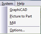
The System Menu enables you to work in different modules of the system simultaneously. The corresponding module button on the toolbar may be pressed to switch to that module.
Figure 3.126. form, Command tab

![[Note]](../images/note.png) |
Note |
|---|---|
|
The toolbars themselves can be modified at all times. To change their position or shape within the module, simply drag or resize them according to your needs. Moving and resizing the toolbars does not require the use of the Customize Toolbar command. This command is only needed when you wish to modify the actual buttons on the toolbars. |
 |
Select from the menu to change the system defaults and parameters, and also to define the measuring method for your job. The Options parameters are set in the System Options dialog box. |
Figure 3.128. GraphiCAD form

| Show Vector Arrows | Display the vector arrows on screen in order to show the entities direction. |
| Show Markbox Dimensions | Add markboxes that show the height and width of selected entities. You can also change these values by clicking on the boxes and entering the new values or by pressing Enter to execute the changes. |
| Multi Options click | Determines the default-working mode for the creation of Tangents, Trims, Blends and Chamfer. When this option is checked, the system will automatically present all possible solutions and you must pick one. If left un-checked, the system will select the best choice from the possible solutions. At all times you may view all of the options. This switch may only be set in the default mode. |
| Undo Depth | Reverses the last change made in the Edit mode. The GraphiCAD is defaulted to save 30 actions. |
| Loop Tolerance | A loop is a section of an entity that has overlapped itself. Loop Tolerance will ignore any loops lower than the figure inserted in the text box. |
| Gap Tolerance | Gap Tolerance will ignore any spaces between two entities greater than the figure inserted in the text box. Separate entities below this value will be connected. |
| Text Parameters | Enter the default values for the text parameters to appear when opening the Text Toolbox. |
Figure 3.129. Dimensions form

| Font | Enables you to set the default dimensions font style. |
| Font Size | Enables you to set the default dimensions font size. |
| Arrow Head Size | Enables you to select the size of the dimension arrow head. |
Figure 3.130. form
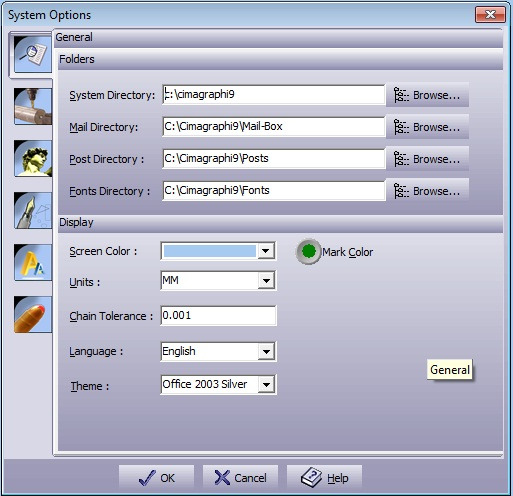
| System Directory | Defines the location of all the system files. This includes the executable files, DLL's, libraries, help files, and utility files. To change this directory, use the button on the right and point to a new directory. |
| Mail Directory | Defines the location of all the temporary files, including the private clipboard files, backup files and temporary files. To change this directory, use the button on the right and point to a new directory. |
| Posts Directory | Defines the location of all the machine drivers. This includes the provided post-processors. To change this directory, use the button on the right and point to a new directory. |
| Fonts Directory | Defines the location of all the fonts provided with the system. The system will automatically detect the Microsoft Windows™-provided True-Type fonts or any other True-Type font properly installed in Windows™. To change this directory, use the button on the right and point to a new directory. |
| Screen Color | Select the preferred background color. |
| Units | Set the work-mode units (mm or inch). |
| Language | Select the language of the system. |
| Chain Tolerance | Define the system wide size for chaining. This value defines the smallest gap to be automatically closed by the system. |
| Show Scales | Define which scales to view by checking the scales you need. |
| Advanced Dialog | When marked, all forms will open in advanced mode. |
| |
 |
|
| Transform Menu |  |
Help Menu |