| View Menu | ||
|---|---|---|
 |
Chapter 5. Mill |  |
| View Menu | ||
|---|---|---|
| |
Chapter 5. Mill | |
Figure 5.9. View Menu

Figure 5.10. View Zoom Sub Menu

 |
Show the entire job. | Ctrl-A |
 |
Expand the job by a factor of two. (A roller-mouse can be used for this operation). | Ctrl-D |
 |
Reduce the job by a factor of two. (A roller-mouse can be used for this operation). | Ctrl-H |
 |
Define a window for new scale. | Ctrl-W |
 |
Jump to the previous zoom. | Ctrl-P |
 |
Show the selected entities (those who are marked). | Ctrl-L |
Figure 5.11. View Rotate Sub Menu

 |
Click once to perform a single movement, double-click to perform multiple movements. To remove the coordinate system click on the icon. For more control use the arrows keys to rotate. Pressing the Shift key while using the arrows will rotate the view in smaller steps.
Figure 5.12. Manual Rotate Axis  Red color of the axis name indicates that the axis is pointing toward the viewing point. Blue indicates that the axis is pointing away from the viewing point. |
Ctrl-R |
 |
Top (XY) view. | Ctrl-Alt-R |
 |
X-Z view. |
 |
Z-X view. |
 |
Y-Z view. |
 |
Z-Y view. |
 |
Isometric view. | Ctrl-Alt-I |
 |
Define a grid to be displayed on the screen. Use this grid as a reference when operating on the image. Two grid types are available: rectangular and isometric (triangular). Refer to the grid points by selecting the mouse grid cursor. The grid is displayed by a rectangular net of small user-defined color crosses or by a net of isometric triangles. The grid is a background reference only and cannot be copied to the clipboard.
Figure 5.13. Grid Parameters Dialogue 
Figure 5.14. Grid Display Options 
|
 |
Show or hide the billet. To , select this option from the menu, or press Ctrl-B. Selecting this option again will extinguish the billet from the screen. The function is a toggle mode. Use this function to hide or show the billet. |
 |
are the actions the cutter does outside of the material. The rapid motion is displayed as a red dashed line rising from the material, then moving at the retract plane and entering the material at the next milling point. This option is used to show or hide these rapid motions. To show , select this option from the menu. Selecting this option again will turn off the display of the rapid motions. This function is a toggle mode. |
 |
Activate the simulation process. You must wait until the calculations end and the simulation starts. You will see a solid 3D image display of the real part you created, according to the toolpaths that you selected to be simulated (by marking). The simulation calculations continue until the toolpath is finished and the final product is displayed. The simulation function will prompt you to mark the simulation resolution. The simulation actually displays the final part after the selected tools and toolpaths have removed the material. This function is useful for easy detection of errors in the part or for visualization. You may also check surface smoothness and gouging. Figure 5.15. Simulation Dialogue 
After the simulation is finished you can apply several display functions on the simulated object such as zooming, rotating, panning and changing the material parameters. To quit the Simulation mode, select the Simulation command from the View menu again or press Simulation again. Figure 5.16. Simulation Example 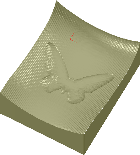
|
To view a fast simulation of the tool's movement, mark the desired group and select from the menu. The display on both options is a colored circle in the size of the defined tool moving along the selected toolpath.
 |
Select in order to view the tool movement on the upper plane of the billet. |
 |
Select for the real depth view. |
| |
 |
|
| Edit Menu |  |
Setup Menu |