| Edit Menu | ||
|---|---|---|
 ֲ ֲ |
Chapter 4.Picture to Part | ֲ  |
| Edit Menu | ||
|---|---|---|
| ֲ |
Chapter 4.Picture to Part | ֲ |
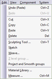
Figure 4.8. Edit Menu
 |
Reverses the last change made. is a repetitive command. The number of Undo levels is defined in the
Activate either by selecting this option from the menu, by pressing Alt-BackSpace, or by pressing shortcut button. |
 |
Deletes the marked entities from view and sends them to the system clipboard. In Component mode, marked groups are . In Assembly mode, marked surfaces are . The clipboard may be treated as an additional datastack, holding the entities sent to it as raw material ready to be restored at the desired time. A entity disappears from the screen. An element must be marked before it can be . Select from the menu or press Ctrl-X to cut an element. |
 |
Takes the entities and sends them to the system clipboard in a similar manner to the command. However, all entities remain on the drawing. An element must be marked before it can be copied. Select from the menu or press Ctrl-C to copy an element. |
 |
Takes the system clipboard contents and inserts them into the drawing using the original coordinates. In Assembly mode, a previously replicated object is pasted as a new component. Select from the menu or press Ctrl-V to paste an element. |
 |
To delete an object, in Component mode, once a geometry is marked included, it. In Assembly mode, marked surfaces will be deleted. Select from the menu or press Delete to delete. Delete is recoverable with the Undo command. |
 |
Figure 4.9. Edit Sculpting Tool Dialogue  This powerful tool enables you to create the Picture to Part surface manually by defining an Active Tool cursor and choosing an action from the list. Select from the menu; the 3D Paintbrush Manager appears in the Macro Panel. The 3D Paintbrush dialog box is divided into several areas:
To activate and deactivate the tool, select ג†’ from the menu, or press Ctrl-T. Mouse vs. Pen:ֲ The system uses the pen as a pressure-sensitive mouse. Whenever the mouse is selected, pressing the button is considered a full pressure pen operation.
|
 |
Sketch enables you to create geometries within the Picture to Part module. The tool is extremely useful in Reverse Engineering (importing Cloud of Points files) and then defining areas to be embossed or machined on the fractal surface. Figure 4.10. Sketch Dialogue 
|
 |
The tool produces an image of interwoven lines with differing Z values. Using the function produces 3D curves, to convert to a 3D surface, weave flowlines need to be embossed. This process is described at the end of the section. Figure 4.11. Weave Surface  To activate select from the menu; the following dialog box appears: Figure 4.12. Edit Weave Dialogue 
To create a 3D effect on the woven surface, you will need to use the Emboss Ruled Surface function. When working with a woven image of more than one Knot each Knot needs to be embossed separately. To emboss a single knot: Mark a single level and select from the ; the single flowline appears in the Emboss Ruled Surface work area. Right-click, and from the menu select . Click on any Corner Control Point; a wire frame surface is displayed. From the Surface section in the Macro Panel ensure that the Into Volume radio button is selected. Select to start the surface creation process. When embossing subsequent Knots, unmark the flowline you have just embossed and mark a new Knot. These operations can be performed in the Group Panel. Right-click on the Emboss Ruled Surface work area select ג†’ ; right-click again and select ג†’ ; the next marked knot appears. Right-click, and from the menu select . Click on any Corner Control Point; a wire frame surface is displayed. From the Surface section in the Macro Panel ensure that the Into Volume radio button is selected. Select to start the surface creation process. Two emboss subsequent knots follow the procedure described in the last two paragraphs. |
 |
Enables you to create 2D geometries from cutting the surface with a horizontal plane (equi-Z surface). This command is useful for designing parting lines to surface. Selecting this menu item brings up the Z Equal Level dialog box: Figure 4.13. Edit Z Level Group Dialogue  The red numbers identify the higher and lower levels that the surface reach. These are the limits for the Z level input box. Enter a value and press to start calculating the geometry. The result is a 2D group, residing at the Z level and identifying the intersection between the surface and a planar surface at the specified Z level.
|
 |
Project a 2D contour over the Picture to Part surface. The 2D contour will become a 3D contour. |
 |
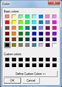
Select the material you want to add to your material collection, and define the different lighting parameters that will affect the display of the surface. Figureֲ 4.14.ֲ Edit Z Level Group Dialogue 
|
 |
Measure evaluates vertical, horizontal and diagonal distances as well as angles between two points. After you select the measure function, a rectangle with eight control points will appear on screen followed by the measure dialog box. Move the control point to the desired locations in order to get the distances and angles between the rectangle control points. You can continue measuring until the Measure dialog box is closed. The values in the measure dialog box can be copied into the Windows clipboard by marking the value you whish to copy (make it appear with blue background) press the mouse button and select from the pop-up menu. |
| ֲ |
 |
ֲ |
| File Menuֲ |  |
ֲ View Menu |
![[Note]](../images/note.png)