Component Menu

Figure 4.28. Component Menu

Component menu

Abstract

The Component Menu is the basis for all the fractal and mesh surface manipulation commands. It is from here that you work with individual geometries and surfaces.

[Note] Note

The Component Menu cannot be used when in assembly mode.

  • New Component: Opens new component tab.

  • Emboss: Takes 2D shapes and emboss them due to cross section and symmetry definitions.

  • Emboss Ruled Surface: Sections that may vary along straight/curved flowlines.

  • Shade Analysis: Takes a bitmap, applies filters and converts it into 3D.

  • Design Surface: Design simple mathematical mesh surfaces.

  • Texture: Applies repetitive 3D textures on the embossed surfaces. These textures are user-defined and may involve random parameter to give some "handmade" touch to the textures.

  • Smooth: Smoothes the surface.

  • Equalize: Reduces "noisy" surfaces to be flattened.

  • Offset: Real 3D offset to the surface.

  • Touch: Handmade effect given to the fractal surface.

  • Trim: Trim surface walls.

  • Align to Horizontal: Align surface to the XY plane.

  • Reset: Resets whole or marked surfaces back to its initial status.

ComponentNew

New component

Creates a new Component tab.

ComponentEmboss

Emboss

The Emboss function applies a characteristic cross section on the area bounded by a closed or open 2D group. A group may contain one or more contours. A group that contains a number of closed shapes will automatically cause the system to use an in-out algorithm in order to define what is in and what is out. Areas that are in will be affected, and areas that are out will not be affected. Emboss may be applied to open contours with fade effect.

To display the Emboss Definition dialog box, select the Emboss option from the Component menu, click on the icon, or press F2. The dialog box below appears:

Figure 4.29. Select Groups Dialogue

Select groups dialogue

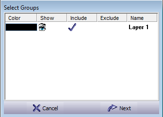
You should set the groups for embossing: Select the Inc (Included) group for groups to be embossed. Select the Exc (Exclude) group for groups to be ignored by the embossing process. At this stage you should press Next to continue, or Cancel to stop.

Figure 4.30. Setting Parameters For Embossing Dialogue

Setting parameters for embossing dialogue

In this dialog box, you may view and edit the cross section. This view holds two definitions: the Section and the Symmetry. Pre-defined sections are displayed on the right side of the dialog box. Select one of these pre-defined sections to apply this cross section to the geometry. The bottom part of the dialog box displays switches that define the way in which the section will be applied on the surface.

There also features an advanced window function. Press on the Advanced mode button icon to open the file retrieval window.

<paste> Pastes the system clipboard to be a cross section. To do this, the marked clipboard has to be a single value chain (never same X for two different Y's) and open in the left to right direction (growing X).
Linear Slope Creates a linear slope section. You will be prompted to enter a slope angle in the Angle edit box.
Circular Arc Defines a circular arc section. You will be prompted to enter the arc's opening angle.
Extrude Sets the section into a block form on the positive side of Absolute Z Zero. No parameters except the Z are required.
Ellipse Defines an elliptic section. You will be prompted to enter the Aspect ratio (the ratio between height and width).
Angle/Aspect Enter this value to define the Linear Slope and Circular Arc sections. For the Ellipse section this parameter changes to Aspect.
Apply Commit the changes you defined to the Emboss View window. You can also reset changes to the original section by pressing this button.

Setting Embossing Parameters - Section View.  Each cross section can be customized, and control points on the sections may be edited. These control points are indicated by small circles (curve control points), or small rectangles (end control points). Pressing the right mouse button over this area invokes a pop-up menu.

Circle Defines a control point of the spline curve. Moving this line will affect the curve between two rectangles.
Rectangle Defines ends of curves. Each curve is built from two rectangles and one circle. Moving a rectangle will translate the end point of the curve and effect the two curves that are connected to it.
Yellow line Indicates a tangent between two neighboring curves. A yellow line appears each time there is a combination of two control points (circles) and an end point on one line.
Dashed Sky Blue Line Drawn between a control point and the two end points on the same curve.
Full Sky Blue Line Drawn between two neighboring control points.
Red Curve The red curve describes the cross section that will be used to create the surface. You can change the cross section by moving the control or the end points and by selecting different parameters in the angles input fields.
Horizontal Line Indicates the surface relative to zero. If you define a section beneath this line it will make a surface with a de-bossed (negative emboss) section.
Vertical Line Used for displaying the symmetric characteristic of the section. It acts like a mirror so that each curve on the left side is mirrored on the right side. Only the left side of the section definition window can be edited, and the right side is changed respectively.
Filled Rectangle This rectangle has a special kind of end point, which is located on the vertical line. It is used for adding and deleting control and end points, and also for moving the center of the section in the Z-axis. You cannot move this rectangle in the X-axis because the section must be symmetric.
Adding Curve You can add up to 256 curves (total) for defining a section. Add a curve by pressing the left mouse button on the filled rectangle and dragging the new rectangle to the chosen location.
Deleting Curve Delete a curve by moving a rectangle to the filled rectangle. Press the left mouse button on the chosen rectangle, drag it to the filled rectangle location and drop it there. Or delete a curve by pointing on a circle or rectangle and press Ctrl-Del. Selecting Delete from the pop-up menu can delete the point under the mouse cursor.
Moving Full Rectangle To move the full rectangle on the vertical line, press the left button on it and move the mouse to the right, and then move it up and down. Moving the mouse to the left will create a new control or end point.

[Note] Note

In order to prevent creation of negative angle walls when moving control points, the end points also move when such a situation occurs.

Table 4.3.  Section Definition

Side Angle The angle between the zero level and the section. This field may be modified by the user and applied on the section pressing the Apply Angles button.
Top Angle The angle at the top of the section. This field may be modified by the user and applied on the section pressing the Apply Angles button.
# Ctrl Points Number of control points that are used to create the section (small circles).
X,Y The coordinates of the cursor in the section creation window. This value is displayed normalized to the Z parameter value and will be displayed only if the Z value is greater than zero.
Tolerance Low/High This track bar controls the smoothness of the section.
Fit To Y Move the scroll bar and display the whole section by zooming. This switch can be activated/deactivated by clicking on the checkbox or by reselecting this option from the pop-up menu or pressing Ctrl-A.
Tangent Keep the tangent properties between two curves. End point A is between two other end points on the same line. There is one control point on either side of A. If either control point is moved, A moves to remain tangent to the line. Moving the control points fast disables this tangent connection feature. This mode is activated/deactivated by checking the Tangent box or by the pop-up menu option Ctrl-T.
Flip Z Mirror the section relative to the Z-axis. Creates a female section. This option is activated by pushing the button or by selecting it from the pop-up menu Ctrl-Z.
Height Enter the Z height of the section center. The center point of the highest cross section will have this value when creating the surface.

Figure 4.31. Cross Section Menu

Cross section menu

Load Load *.sct section files.
Save As Save *.sct section files.
Copy Copy the section to the system clipboard.
Reset Loads the Ellipse section.

Table 4.4.  Surface Type

Fractal Emboss using fractal method.
Mesh Emboss using mesh method.

[Note] Note

A component can only hold surfaces of one type - fractal or mesh.

Table 4.5.  Emboss Type

Stretched Sets the maximal height of the embossed surface to the widest point in the embossed contour. From this point on, the system stretches the cross section for every local point of the embossed surface. The result will be smooth embossing but the edge side will not be maintained.
Edge Angle Gives the first priority to the cross section angle and gives the embossed surface a constant edge angle. The result might give sharp edges or flat top for the embossed surface, relative to the local width of the embossed contour.
Cross Section Gives the first priority to the cross section shape, scaling it to become larger or smaller to fit the embossed geometry. The maximal Z height is derived from the maximal width of the embossed contour.
Rubber Rubber, acts like Stretched function with an increased smoothing operation. The system stretches each local point of the emboss surface and adds additional smoothing algorithms.
[Note] Note

Works for fractal only!

Setting Embossing Parameters - Symmetry View.  Each cross section can be embossed in a symmetric or a non-symmetric way. The non-symmetry feature let you sculpt special effects such as water drops, cloth folds and so on. To get into the symmetry definition, select Symmetry at the top of the section view.

Figure 4.32. Setting Parameters For Embossing Symmetry Dialogue

Setting parameters for embossing symmetry dialogue

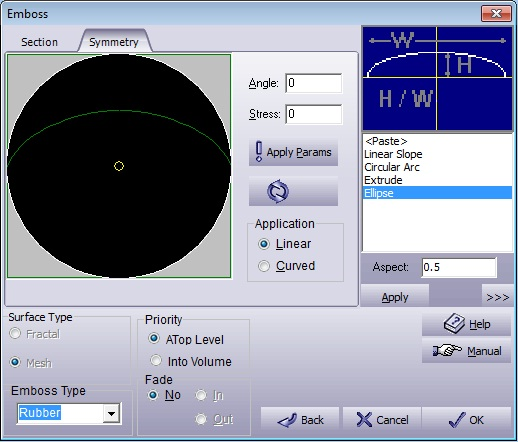
As shown, the elliptical default section is displayed stretched (embossed asymmetrically). The embossing is influenced to the 45° direction. The stress value is on the scale of 0 (symmetric) to 1.0 (most influenced). Changing the stress direction and magnitude can be done either by typing the values into the edit boxes and pressing Apply Params, or by dragging the small circle around with the mouse.

Reset Retrieves the influence to 0.0 (fully symmetrical).
Application

Sets the influence shape as follows:

Linear The influence is linearly affected by the distance from the part center.
Curved The influence is affected by both the distance from the part center, and a wave shape.

Figure 4.33. Symmetric Embossing Example

Symmetric embossing example

Figure 4.34. Asymmetric Linear Slope Example

Asymmetric linear slope example

Figure 4.35. Asymmetric Curved Slope Example

Asymmetric curved slope example

Merge Into Part.  The sections can be embossed in two different combinations:

  • Atop Level

  • Into Volume

Atop Level

This option adds the current embossment onto the already existing surface geometry.

Figure 4.36. Atop Level Example

Atop level example

Into Volume

This method combines the current embossment with the existing surface geometry.

Figure 4.37. Into Volume Example

Into volume example

Fade open contours.  Select In/Out to commit fade affect on the section. When this option is not selected, open chains will be closed automatically by imaginary straight lines. This option applies only to open chain images.
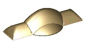
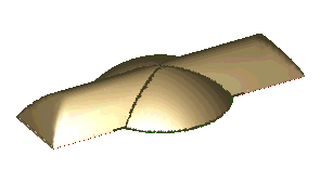
In Lead to increased embossment on chains in the embossed geometries. This option applies only to open chain images.
Out Lead to decreased embossment on chains in the embossed geometries. This option applies only to open chain images.

Figure 4.38. Fade Geometry

Fade geometry

Figure 4.39. Fade Disabled

Fade disabled

Figure 4.40. Fade In

Fade in

Figure 4.41. Fade Out

Fade out

Emboss ruled surface

The Emboss Ruled Surface function is similar to the Emboss command. A characteristic cross section will be applied on the area bounded by the 2D group. A group may contain one or more contours. To activate select Emboss Ruled Surface from Component menu or click on the relevant icon. A wizard will walk you through the process of creating the ruled surface.

Surface Type. 

Figure 4.42. Wizard Page 1, Surface Type

Wizard page 1, surface type

We can select from creating a surface from a single flow line (I), creating a surface from two flow lines (II), and creating a surface from two flow lines and a Z guide line (III).
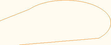
Surface from: I,II,III Picture: Method: Restrictions:
Single flow line. ruled single We need to define single flow line by clicking on it on the screen. None, even from a regular line we can make a ruled surface
Two flow lines. two flows We need to select two different flow lines. We must have two different flow lines in separate layers.
Two flow lines and a z guide line. 2 flow with z We need to select two different flow lines and an embossed flow line as z guide line. We must have two different flow lines in separate layers, and an embossed part for Z guide line.

First we need to click on the flow line we need, afterwards we can select a starting point by clicking on the "set flow line starting point button".ruled surface starting point 

Another option we can use is to set the flow line direction by clicking on the button ruled surface direction 

This is how the start point and the direction looks like:ruled surface exmp 

After we finished setting up the flow line we will press next and receive the parameters page

parameters,

Figure 4.43. Wizard Page 2, Parameters

ruled surface param

The parameters we can use are:

Section alignment: normal alignment or vertical alignment.

Contour type: the contour type we use lines or curves.

Edges: the surface edge from upper right to left, upper left to right and center.(in two flow lines and two flow lines with a z guide line we have only the center edge)


Figure 4.44. Wizard Page 2, sections

ruled surface sections

On the sections part we can choose how our surface sections will look like.

We can copy a section to use or use an old section we used by copying it and paste it on the section preview, after every change we made on the section preview we need to press on apply button .ruled surface apply

We can also save the section we used so we can use it later on a different project.

These buttons written under display the capabilities of creating a surface by placing sections as we require and we can use different sections on the same part.

Button Image: Definition: Comments:
ruled pick Pick section.
ruled add Add Section After we choose add section we need to click on the flow line.
3.jpg Remove section After we choose remove section we need to click on the place we want it to delete.
4.jpg Remove all sections
5.jpg Break flow line to add section. Adds a new point on the flow line.
6.jpg Swap entity type.

When the section we wish to add is ready we just need to add him to the surface by using the marking on the flow lines, afterwards we will directly receive the result.

and don't forget we can always remove the section if the result is no good for us.

ComponentShade Analysis

Shade analysis

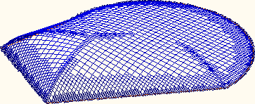
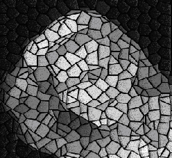
This function creates a 3D surface based on the picture shade analysis. Choosing this command from the menu, or pressing the button, or pressing F4 will bring up the following dialog box:

Figure 4.43. Select Groups Dialogue

Select groups dialogue

You should set the groups for shade analysis: Select the Inc (Included) group for groups to be embossed. If no groups are marked, you can press Next anyway. The bitmap will be completely embossed, regardless if there are any groups. Select Next to open the file retrieval window. Select the picture you want to emboss. Select Open; for the following embossing dialog box to open:

Figure 4.44. Shade Analysis Definition Dialogue

Shade analysis definition dialogue

This command performs calculations regarding the shades on the surface according to the previously defined parameters in the Shade Analysis Definition dialog box. This dialog box is divided into four main sections:
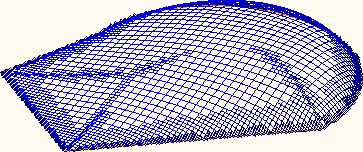
  • Picture window: This window contains the analyzed picture. The user can click over it and get the color value beneath the cursor. This window can work in single (default) mode or in repetitive mode, as selected with the tabs above the picture.

  • Palette area: This area has several scroll bars and a graph area. The graph area shows the original grayscale and modified colors. The user can drag and modify this graph on the palette area. The grayscale can be modified anywhere between 0 and 255. Grayscale graph Right clicking the Picture Window will display a small blue/white circle on the graph representing the selected color level.

    Right clicking the graph area, a pop up menu appears with Edit Values. Pick it to get the following dialogue:

    Figure 4.45. Shade Analysis Definition Dialogue

    Shade analysis Z input dialogue

    From Low gray level.
    To High gray level.
    Value Z Height.
    Constant All gray levels between From and To will have the same Value Z value.
    Difference Starting from From gray level, the value is incremented by Value Z to To.

    You can edit each cell manually.

  • Filter area: This area includes six (6) filters that may affect the picture. A value input field is available to give necessary parameters for the filtering process.

  • Geometry area: This area includes controls that define the properties of the embossed surface.

Open file
Opens a picture file. Acceptable formats are: BMP, JPEG, PCX, TIF, GIF.
Single Single embossing for the selected bitmap.
Multiple

Makes the embossing area of tiled bitmaps which are repetitions of the selected bitmap file:

Height # Number of repetitions in the Y direction.
Width # Number of repetitions in the X direction.
Flip

No Flip All repetitive bitmaps are embossed in the same orientation.
Flip Horizontal Reverts every even column of tiles. Tiles will match along the left and right edges.
Flip Vertical Reverts every even row of tiles. Tiles will match along the top and bottom edges.
Flip Both Reverts every even row or column so bitmaps will match along four (4) edges.

Fit Stretches the picture to fit the display window in the dialog box.
Brightness Controls the amount of light to which the picture will be exposed.
Contrast Defines the relation between dark and light. Positive changes produce a wider range of luminance. Negative changes produce a narrower range of luminance.
Levels Selects the number of gray levels with which you want to display the picture. Two gray levels will produce a black and white picture. More gray levels will result in a more accurate display of the surface created from the picture.
Filters

Originl

Resets the bitmap to its original gray scale colors.

Original filter

Engrave

Changes the bitmap to a series of horizontal lines with varying widths - up to the value declared in the Value field.

Engrave filter

Mosaic

Changes the bitmap to constant color polygon. The polygon size is set by the Value field.

Mosaic filter

Oil Paint

Alters the bitmap picture to a less sharp image, giving an oil paint effect.

Oil paint filter

Inverse

Reverses the grayscale value within its 256 shades.

Inverse filter

Edge

Emphasizes the edges of color groups.

Edge filter

Exclamation mark
Apply the changes to the displayed picture according to the selected values.
Reset Shows the picture in the original form.
Anchor Selects the zero location of the surface to be produced.
Dimensions Enters the surface width and height values. If no group is marked, the default is the actual picture size in units (that is derived from the DPI defined in the FileOpen dialog). If marked groups exist on the layout, the picture dimensions will be set automatically to match this size.
Position Selects the X,Y position of the surface. If marked groups exist on the layout, the picture position will be set automatically to fit in the marked area.
Shade analysis
This set of nine (9) buttons covers the most common points to indicate the "sun" location in order to choose the shade orientation. The picture of the tree (below) demonstrates the real shade location on the surface.
Surface

Z Max Selects the surface maximum Z height.
Z Min Selects the surface minimum Z height.
Tol Enters the minimal patch size in units or percent. The smaller the value, the result will be closer to the bitmap image.
Smoothing There are four (4) levels of smoothing for creating a shading surface from the picture (No Smooth, Smooth Lite, Smooth Med, and Smooth Heavy). Use smoothing to reduce the amount of disturbances in the picture that cause a rough surface. The Smooth Heavy level will reduce the disturbances efficiently and create the smoothest possible surface.
Atop Surface This option adds the current embossment onto the existing surface.
Into Volume This method combines the current embossment with the existing surface geometry.

Select OK to apply changes. Select Cancel to exit the function without changes.

Figure 4.46. Shade Analysis Example

Shade analysis example

ComponentDesign Surface

ComponentDesign SurfaceDefine Surface

Define surface

Create mathematically definable surfaces. Select this menu item to create the following surfaces through the simple dialog box:

  • Spherical: A sphere.

  • Cylindrical: A cylinder that it's main axis is parallel to the X or Y axis.

  • Conical: A trimmed cone that it's main axis is parallel to the X or Y-axis.

  • Function: Define your own surface using math functions in either cartesian or polar coordinate system.

  • Plane: A rectangular patch of a non-vertical planar surface.

  • Ellipsoid: An ellipsoid.

  • Toroid: A torus.

  • Dual radius surface: Two radii define this surface in the XZ and the YZ planes.

The Range section in the dialog sets the surface boundaries. The range is rectangular, except for the function polar system where the range may be defined by different angle/radius:

Figure 4.47. Define Surface Range Input

Define surface range input

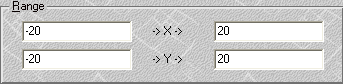
Define the range of minimal and maximal -> X -> and -> Y -> values to define the patch limits. Press OK to accept the setting for the surface. Exit without changes by pressing Cancel. Press Help to open the On-line Help.

Spherical Surface.  To define a spherical surface, select Sphere tab. The Define surface dialog box should look like the dialog box below.

Figure 4.48. Define Surface Sphere Dialogue

Define surface sphere dialogue

Top Defines the surface as convex.
Bottom Defines the surface as concave.
Sphere Center These coordinates define the sphere's center point. Set the Z value so that the surface is easy to setup later on the machine.
R Defines the radius of the sphere.

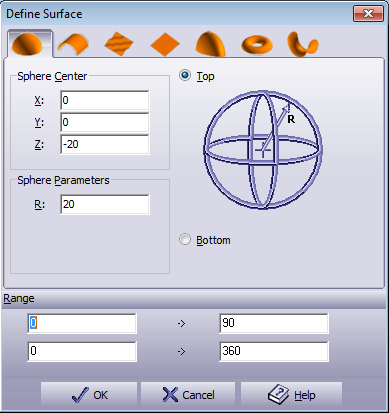
Conical and Cylindrical Surface.  To define a conical or cylindrical surface, select the Cone tab. The following dialog box appears:

Figure 4.49. Define Surface Cylinder Dialogue

Define surface cylinder dialogue

Top Defines the surface as convex.
Bottom Defines the surface as concave.
X axis/Y axis Defines the axis along which the cone lies.
Cylinder Center Defines the cone's center point. Set Z so that the surface is easy to setup later on the machine.
R1 Defines the radius of the cone.
R2 Defines the second radius of the cone. Let R1 = R2 to define a cylinder. Let R2 = 0 to end the cone at a point.
L Defines the distance between the ends of the cone.

Figure 4.50. Cone on X-Axis, Bottom

Cone on X-Axis, Bottom

Function Surface.  To define a surface by a function, select Function tab. This option creates a surface by interpreting the given mathematical function. The following dialog box appears:

Figure 4.51. Define Surface Function Dialogue

Define surface function dialogue

Function Name This field is the user description of the function. To change a given name simply use the function name Edit box at the top of the dialog box.
Function

This field is the actual function that will generate the surface. To edit a function, use the Function Edit box at the top of the dialog box. This field is the active function, regardless of which item is marked in the list of pre-defined functions. A function can be either Polar or Cartesian. Enter the function Z= f(X,Y) or Z= f(R,A).

The function supports the following operators :

+ Plus
- Minus
* Multiply
/ Divided
^ Power
ASIN Arc Sinus
ACOS Arc Cosine
ATAN Arc Tangent
SIN Sinus
COS Cosine
TAN Tangent
LOG Log
EXP Exponent
SQR Square root
ABS Absolute
INT Round to closest integer

[Note] Note

Make sure to open and close the correct number of brackets to achieve correct results.

Examples: Cartesian Polar
SQR(X^2+Y^2)*SIN(X/1000) COS(A)+8*LOG(R)
COS(X)*EXP(SQR(Y)) SQR(R/3)

Range These coordinates define a rectangular area in the XY plane or circular area in the RA plane. Enter the limits of these surfaces.
Save
Save a new function or to overwrite an existing function. The system stores each function in a separate file (*.fun). These files should be stored in the systems directory.

Planar Surface.  To define a planar surface, select Plane tab. The following dialog box appears:

Figure 4.52. Define Surface Planar Dialogue

Define surface planar dialogue

P1

Coordinate of first point for plane definition.

X X Coordinate.
Y Y Coordinate.
Z Z Coordinate.

P2

Coordinate of second point for plane definition.

X X Coordinate.
Y Y Coordinate.
Z Z Coordinate.

P3

Coordinate of third point for plane definition.

X X Coordinate.
Y Y Coordinate.
Z Z Coordinate.

Range These coordinates define a rectangular area in the XY plane or circular area in the RA plane. Enter the limits of these surfaces.

[Note] Note

Make sure that the 3 points create a surface. For example, make sure all three points differ one from one another, and that they are not aligned.

Ellipsoid Surface.  To define an ellipsoid surface, select the Ellipsoid tab. The following dialog box appears:

Figure 4.53. Define Surface Ellipsoid Dialogue

Define surface ellipsoid dialogue

Ellipsoid Center

X, Y, Z Represents the ellipsoid center.

Ellipsoid Parameters

Rx, Ry, Rz Defines the 3 radii of the ellipsoid. Keeping all three radii equal will create the perfect sphere.

Top Defines the surface as convex.
Bottom Defines the surface as concave.

Toroid Surface.  To define a toroid surface, select the Toroid tab. The following dialog box appears:

Figure 4.54. Define Surface Toroid Dialogue

Define surface toroid dialogue

Toroid Center

X, Y, Z Represents the toroid center.

Toroid Parameters

R1 Defines the inner radius of the toroid.
R2 Defines the radius of the toroids in the inner tube.

Top Defines the surface as convex.
Bottom Defines the surface as concave.

Dual Radius Surface.  To define a dual radius surface, select the Dual Radius tab. The following dialog box appears:

Figure 4.55. Define Surface Dual Radius Dialogue

Define surface dual radius dialogue

Peak

X, Y, Z Defines the peak or epi-center of the dual radius surface.

Parameters

Rx Defines the radius in the X-axis. The value may be positive or negative.
Ry Defines the radius of the Y-axis. The value may be positive or negative.

ComponentDesign SurfaceExtrude

Extrude

To create a drive for a surface, select Extrude from the Design Surface in the Component menu. The section to be extruded is the marked group from the Group List. The following window appears:

Figure 4.56. Extrude Dialogue

Extrude dialogue

A preview of the extrude section will appear in the box on the right. While editing this dialog box, use View options to preview the design before accepting it.

Drive Start Enter in a value to begin the drive point.
Drive End Enter in a value to end the drive point.
Apply
Apply the changes you made to the preview window.

Press OK to create an extrusion surface. Exit without changes by pressing Cancel. Press Help to open the On-line Help.

ComponentDesign SurfaceRevolve

Revolve

This option is used to create a surface of revolution. The section to be revolved is the marked group from the Group List. The following dialog box appears:

Figure 4.57. Revolve Dialogue

Revolve dialogue

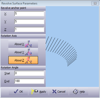
A preview of the rotation section will appear in the box on the right. While editing this dialog box, use View options to preview the design before accepting it.

Revolve anchor point The anchor point of the axis of rotation. Enter in a value for the revolving anchor points on the X, Y, and Z-axes.
Rotation Axis Choose a rotation axis from the three choices.
Rotation Angle

Start Determines the coverage of the body surface. Enter a starting angle.
End Determines the coverage of the body surface. Enter an end angle.

Apply
Apply the changes you made to the preview window.

Press OK to create an rotation surface. Exit without changes by pressing Cancel. Press Help to open the On-line Help.

ComponentTexture

Texture

The Picture to Part module has simplified applying textures on a surface. You can now create almost any image as texture and apply it to the surface. Using this option you can create new user-defined 3D textures.

To define a new texture, mark geometry and send it to the clipboard. Then select the ComponentTexture option. Selecting this option will prompt you with the following dialog box:

Figure 4.58. Select Groups Dialogue

Select groups dialogue

Select the groups to be affected by the texture command. Pressing Next will lead to the Texture Input dialog box:

Figure 4.59. Texture Dialogue

Texture dialogue

Texture width
Enter the width of patterns and the space between each pattern (in % of pattern size) along the horizontal axis.
Texture height
Enter the height of patterns and the space between each pattern (in % of pattern size) along the vertical axis.
ToStretch Distorts the texture shape according to the ratio between the width and the height of the pattern. Using this method will cause circles, for instance, to be textured as ellipses.
Handmade (%) This parameter gives "personal touch" to the embossed texture. Each texture element has its unique geometry, with random change from the designed one. Giving a value of 0 will output the designed texture geometries as is, without any random effects.
Advanced mode
Opens the file retrieval window.
Save as
Allows you to save the texture under a selected name to a *.TXR file.
Emboss
Opens the Emboss dialog box for selecting the shape of the section with which you want to create the texture.

To define a new texture, select <paste> at the list box, and the contours from the clipboard will be imported to the texture window.

The texture files can be loaded directly into the Texture Definition dialog box by selecting them from the list.

The texture will be applied inside all marked groups. Unmarked areas remain untouched. After defining the Texture parameters, select Next, to open the Emboss window.

ComponentSmooth

Smooth light
Smooth medium
Smooth heavy
As in sculpting by hand, part of finishing the job is to polish or smooth down rough areas. Picture to Part defines three levels of smoothing: Smooth Light, Smooth Medium and Smooth Heavy. The smooth action will polish and soften the surface area only on those areas that are marked. Areas that are not marked will remain untouched. The smooth function can be repeated for deeper smoothing.

ComponentEqualize

Equalize

This function enables you to flatten a surface between two Z level values into a selected Z value. All the surfaces between these levels will be equalized to the selected value without touching the surfaces outside the selected range.

Figure 4.60. Surface Equalize Dialogue

Surface equalize dialogue

Start Z height Enter the minimum Z value that includes the surface you want to make equal.
End Z height Enter the maximum Z level that includes the surface you want to make equal.
Change to Z Select the Z value to which you want the surface in range to be equal.
Move component to Z=0.0 The component is moved so the Change to Z height becomes 0.

Press OK to confirm your selection, or press Cancel to abort without changes. Press Help to open the On-line Help menu.

ComponentOffset

Offset

Create offset surfaces in the Z-axis. Choose this option from the Component menu, and the Offset Value Entry dialog box will appear. This option enables you to select the offset value.

Figure 4.61. Offset Value Dialogue

Offset value dialogue

To offset desired surfaces:

  1. Select ComponentOffset command from the menu. Offsetting can be either positive (+Up) or negative (-Down).

  2. Enter the offset value (in units) and press OK. The surface will be offset to the selected value.

This function is useful for planning male and female models where a gap exists between the two parts of the model.

ComponentTouch

Touch

A simple tool for giving the embossed surface a "personal touch" making it look like handmade work. The Touch function works over marked areas only. By selecting Touch, the following input dialog box is displayed:

Figure 4.62. Select Groups Dialogue

Select groups dialogue

Select the groups to be affected by the texture command.

Pressing Next will lead to the Add Touch dialog box:

Figure 4.63. Add Touch Dialogue

Add touch dialogue

Touch Type

Gives the following noise effects:

Random This will make the surface look rougher.
Hammered This option will make the surface look flatter in certain regions as if a hammer hit it.
Melted This option will make the surface look smoother in certain regions as if it were heated and beginning to melt down.

Detail Size XY size of each touch point.
Detail Size Z Z height of each touch point.

Press OK to start the touch effect process. Press Back to return to Select Groups dialog box. Press Cancel to ignore this selection. Press Help to open the On-line Help menu.

ComponentTrim

Trim

Trims walls with an angle bigger then selected.

[Note] Note

In the Picture to Part tab of the System Options the Patch approximation (pix) value must be set to 0.

Figure 4.64. Add Trim Dialogue

Add trim dialogue

Trim to

To what height to trim the surface.

Top The wall is trimmed to the highest point of the wall.
Average The wall is trimmed to the average height of the wall.
Bottom The wall is trimmed to the lowest point of the wall.
Zero The wall is trimmed to 0.

Trim angle
From what angle to trim.

Press OK to start the touch effect process. Press Back to return to Select Groups dialog box. Press Cancel to ignore this selection. Press Help to open the On-line Help menu.

ComponentAlign to Horizontal

Align to horizontal
Align surface to the XY plane. Click the surface on three points. The three points are used to define a plane.

ComponentReset

Reset whole
Reset marked
This function sets the surface back to the initial status (zero level). It is possible to reset the entire surface using the Reset Whole option or an area bound by the marked groups using the Reset Marked option.