| Chapter 4. Picture to Part | ||
|---|---|---|
 |
 |
|
| Chapter 4. Picture to Part | ||
|---|---|---|
| |
|
|
Table of Contents

 |
Title bar: Displays the name of the file you are working on. |
 |
|
 |
Main menu: Contains system commands, which are listed in the form of drop-down menus. |
 |
Toolbars: These are shortcut areas, where you are able to add or delete icons from the defaulted list provided. |
 |
Work area: Where surfaces and geometries can be displayed, edited or created. |
 |
Group manager: In Component mode - enables you to handle and edit all the 2D groups imported to this module from other system modules. In Assembly mode, enables you to handle and edit all components and replicas. You can mark, hide, change name and material of each component. |
 |
System toolbar: Enables you to open other modules, and to cut copy and paste objects between them. |
 |
View toolbar: Shortcut buttons for the menu. |
 |
Status bar: The application interaction area with the user. Displays varied information as system units, mouse cursor position etc. |
 |
Design/Assembly toggle button: This toggle button toggles between design and assembly mode. |
 |
Display panel: Controls surface display. |
 |
Assembly tools/Script panel: Displays:
|

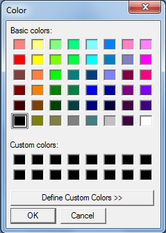
| Color |
When selecting a new layer, a color is automatically chosen for you. If you
decide to select your own representative color for a layer, select the colored
bar for the relevant layer:
 |
|||
| Show | Enables you to select the layers you want displayed on an image. Ensure is selected from the Menu; all the eye icons will be open. To hide or reveal a layer, click on the eye icon. A closed eye icon means the layer is hidden. | |||
Include
|
Include the group with the groups that are affected by the sections operation. A marked group is considered an Include group. Included groups are displayed with a check mark. In addition the marked group in the work area changes to the default marked color; as defined in → . | |||
Exclude
|
Exclude the group from the groups that are affected by the sections operation. A marked group that has been marked with Ctrl pressed is also attributed as an exclude group. Excluded groups are displayed with a check mark. In addition the marked group in the work area changes to the default marked color dotted line; as defined in → . | |||
Mark
|
Indicates whether a surface is marked or not. Click in the area to reveal or hide a check mark. | |||
Priority
|
An integer specifying components priority. | |||
| Name |
To make a layer active click on the layer's name; the layer will be highlighted meaning it is active. To change a layer's name right-click, and select from the menu.
|

|
Ensure the layer you want to display is highlighted, and select Show. To hide a layer, click on the eye icon. Show is a toggle switch operated by clicking on the eye icon. |
|
|
Design mode: Include. Assembly mode: Mark. |
|
| Exclude. | |
| Change group name. | |
| Change Color. | |
| Erase the current layer. All entities in this layer will be deleted (you will be prompted to confirm this action if entities are going to be deleted). | |
| Opens the help file. |
| |
|
|
| Help Menu |  |
File Menu |
![[Note]](../images/note.png)