Assembly Menu

Figure 4.65. Assembly Menu

Assembly menu

Abstract

The assembly mode is a valuable tool, which enables you to work with multiple surfaces simultaneously. This is achieved by using either manual movement with the mouse, or by inserting parameters into the relevant dialog boxes. This module aligns components in parallel and geometric formations, and transforms individual components by moving, rotating, scaling and mirroring them. Click on the Assembly button to activate Assembly mode.

Marking in Picture to Part

In Picture to Part the marking methods differ in Assembly and Component modes. In the Component mode you can mark geometries in three ways: by dragging, right-clicking and using the Group Manager. A marked geometry is indicated by the color selected in SystemOptions.

Dragging Drag over the geometry to create a rectangle. Release the mouse to mark the geometry.
[Note] Note

Partial marking of a geometry will mark the whole geometry.

Right-clicking Right-clicking in the Group Manager section will open a Menu. Select Include or Exclude to mark or unmark a geometry.
Group Manager Click in the Include column of the Group Manager to mark or unmark geometry. The Include column is a toggle function. Click in the Exclude column of the Group Manager to unmark or mark geometry. The Exclude column is a toggle function.

In Assembly mode only whole surfaces can be marked. A marked surface is indicated by control points and animated dotted lines surrounding the surface. To mark drag over the surfaces you require. Partial dragging over a surface will mark the whole surface. An example of a marked surface appears below.

Figure 4.66. Assembly Marked Surface Example

Assembly marked surface example

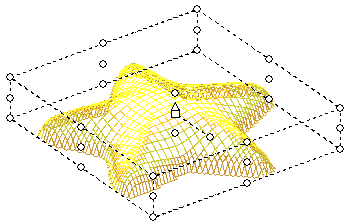
The control points are divided into four areas: the central control area and the top, middle and bottom levels. Dragging the various control points perform specific functions. Below is a table listing the functions of the various control points. These descriptions are for transformations performed manually. Transformations can be performed through the use of dialog boxes.

[Note] Note

  • The reference point is always the centre of the surface.

  • An alteration to the cursor will always occur when the cursor is placed over a control point.

Scaling

X and Y-axis Drag the middle corner control points.
X,Y and Z axis Drag the top or bottom corner control points.

Stretching

X-axis Drag the top, middle or bottom central control points along the X-axis.
Y-axis Drag the top, middle or bottom central control points along the Y-axis.
Z-axis Drag either of the central round control points, not connected with a dotted line. This will stretch the surface up or down.

Rotate

Place the cursor on the central, circular control point connected with a dotted line; the cursor changes into an anti-clockwise arrow. Drag to rotate the surface.

[Note] Note

Rotation only occurs on the X and Y-axis.

Move

Z-axis Place the cursor on the triangle control point in the centre of the surface; the cursor changes into a two-headed arrow. Drag to move the surface up and down only.
X and Y-axis Place the cursor on the square control point in the centre of the surface; a square appears with the cursor. Drag to move the surface along the X and Y-axis.

Copy Press Ctrl while placing the cursor on the square control point in the centre of the surface; a copy icon appears with the cursor. Click the square and drag the copied surface to the desired location.

Marking Multiple Surfaces

There are two methods to mark more than one surface:

  • Drag over the surfaces you require. Partial dragging over a surface will mark the whole surface.

  • To mark specific surfaces press Ctrl and click on the required surfaces; control points will appear. To unmark press Ctrl and click on the selected surfaces; the control points will disappear.

Figure 4.67. Assembly Marked Surfaces Example

Assembly marked surfaces example

The illustration shows four marked stars, as demonstrated by the Control Points surrounding them. In addition the four marked surfaces are surrounded by yellow control points and dotted lines. Dragging the yellow control points performs specific functions to all the marked surfaces, simultaneously.

[Note] Note

  • The reference point is always the centre of the whole marked area.

  • Dragging the white control point will affect each marked surface according to its reference point.

  • Dragging the yellow control points affects all marked surfaces. To alter parameters of an individual surface, only mark the individual surface you require.

Below is a table listing the functions of the various yellow control points.

Scaling Drag the corner control points.
Stretching

X-axis Drag the top, middle or bottom central control points along the X-axis.
Y-axis Drag the top, middle or bottom central control points along the Y-axis.

Rotate

Place the cursor on the central, circular control point connected with a dotted line; the cursor changes into an anti-clockwise arrow. Drag to rotate the surface.

[Note] Note

Rotation only occurs on the X and Y-axis.

Move

X and Y-axis Place the cursor on the square control point in the centre of the surface; a square appears with the cursor. Drag to move the surface along the X and Y-axis.

Copy Press Ctrl while placing the cursor on the square control point in the centre of the surface; a copy icon appears with the cursor. Click the square and drag the copied surface to the desired location.

Assembly Order Panel

Figure 4.68. Assembly Order

Assembly order

Separate surfaces in Assembly mode are all on the same level. The surfaces can be moved into each other forming blended surfaces. To prevent the surfaces from blending into each other there is an option to change the levels order. A surface in a higher order will "climb" the surface in the lower order. This action can be repeated any number of times.

Increase level
Moves marked surface one level up.
Decrease level
Moves marked surface one level down.
Bring to front
Moves marked surface on top all other surfaces.
Send to back
Moves marked surface under all surfaces.
Same level
Places marked surfaces onto the same level.
Trim If more then one component is marked, and one component is in a higher priority then the other. The component with higher priority will be trimmed to the borders of the component with lower priority.

Figure 4.69. Order Example - Same Level, Atop, Trim

Assembly order

AssemblyAlign

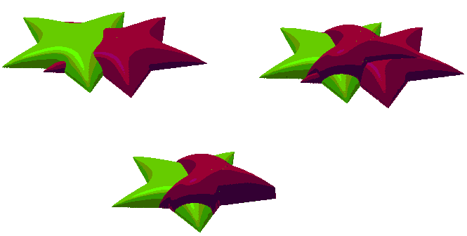
Figure 4.70. Align Panel

Align panel

Positions any number of marked surfaces into a specified formation. Two or more entities need to be marked to operate the functions. To operate align functions select the relevant icon from the Group Panel display, or select Align from the Assembly menu.

Left
Left

Align left example

Aligns the left side of all marked surfaces to the left side of the mark box.
Right
Right

Align right example

Aligns the right side of all marked surfaces to the right side of the mark box.
Center
Center

Align center example

Vertically aligns all marked surfaces according to their individual center point.
Horizontal Spacing
Horizontal spacing

Align horizontal spacing example

Equally spaces on the horizontal, all marked surfaces.
Top
Top

Align top example

Aligns the top all marked surfaces to the top of the mark box.
Middle
Middle

Align middle example

Horizontally aligns all marked surfaces according to their individual center point.
Bottom
Bottom

Align bottom example

Aligns the bottom of all marked surfaces to the bottom of the mark box.
Vertical Spacing
Vertical spacing

Align vertical spacing example

Equally spaces on the vertical, all marked surfaces.

AssemblyTransform

Abstract

Transformation of marked surfaces can be performed manually by using control points, as mentioned in the section Marking in Picture to Part. Alternatively transformation parameters can set by inputting measurements into dialog boxes. Transformations can be performed on single or multiple surfaces. To operate select Transform from the Assembly menu.

AssemblyTransformMove

Move

Select this option to move or copy surfaces to a new location. An anchor may be selected from one of twenty seven points.

Figure 4.71. Assembly Transform Move Dialogue

Assembly transform move dialogue

Absolute Enter the absolute location of the reference point by inserting the coordinate values in the To X, To Y and To Z text boxes. You will also need to select the location of the reference point relative to the frame by selecting one of the twenty seven anchor points.
Relative Enter the By X,By Y, and By Z coordinate values. These allocate where the surface is to move.
Move Select to move the surface to a different location.
Copy Select to move the surface to a different location, and to keep the original surface in its original position.
Anchor Select the location point relative to the frame. This is defined by one of twenty seven radio buttons; there are nine buttons on each of the three levels.

AssemblyTransformRotate

Rotate

Select this option to rotate the active surface. The Rotate Surfaces dialog box appears, enabling you to define the rotation activity on the XY Plane. Rotation within the XY Plane is defined by entering the X, Y coordinates of the rotation center point or by using the anchor radio buttons. Select one of the twenty seven buttons to indicate the center of rotation.

Figure 4.72. Assembly Transform Move Dialogue

Assembly transform rotate dialogue

X Enter the center of rotation X coordinate value.
Y Enter the center of rotation Y coordinate value.
Angle Select this option for rotating the selected entities absolute to the horizontal line.
Rotate Individuals Rotates the marked entities without preserving their orientation against the horizon.
Absolute Angle Rotates the marked entities absolute to the horizon line.
Move Select to rotate the surface to a different location.
Copy Select to rotate the surface to a different location, and to keep the original surface in its original position.
Anchor Select the location point relative to the frame. This is defined by one of twenty seven radio buttons; there are nine buttons on each of the three levels.

AssemblyTransformScale

Scale

Eables you to change the scale of an object. The surface can be scaled or stretched by the X, Y, and Z Scale.

Figure 4.73. Assembly Transform Scale Dialogue

Assembly transform scale dialogue

Scale X,Y,Z Enter scaling values.
Method

By % Select scaling by entering values as percentages.
By size Select scaling by entering values as size.

Fixed Aspect

You can use the fixed aspect ratio between the axis when applying the scale option to keep the surface in a fixed proportion over the selected axis.

None There is no effect of one axis on another. The result is a pure stretch function.
X-Y There is a fixed aspect ratio between the X and Y axis only.
X-Y-Z There is a fixed aspect ratio between all the axis.

Scale Individuals

Scales and keeps the distance ratio between other surfaces.

[Note] Note

This function can only be used with two or more marked surfaces.

Anchor Position Enter coordinate values to select specific anchor location.
Move Select to scale or stretch a surface to a different location.
Copy Select to scale or stretch a surface to a different location, and to keep the original surface in the same location.
Anchor Select the location point relative to the frame. This is defined by one of twenty seven radio buttons; there are nine buttons on each of the three levels.

AssemblyTransformMirror

Mirror

Function enables you to reflect a surface on the X, Y or Z axis of symmetry. The axis of symmetry can be within or outside of the surface.

Figure 4.74. Assembly Transform Mirror Dialogue

Assembly transform mirror dialogue

Flip X,Y,Z Select on which axis the flip is to occur.
Anchor Position Enter coordinate values to select specific anchor location where the flip is to occur.
Move Flip the surface to a different location.
Copy Flip the surface to a different location, and to keep the original surface in its original position.
Anchor Select the location point relative to the frame. This is defined by one of twenty seven radio buttons; there are nine buttons on each of the three levels.

AssemblyReplications

Replications

Rectangle. Select this option to place multiple surfaces around a designed, rectangular matrix.

Figure 4.75. Assembly Replications Rectangle Dialogue

Assembly replications rectangle dialogue

By X Enter the amount of space between surfaces on the horizontal plane.
By Y Enter the amount of space between surfaces on the vertical plane.
Copies X Enter the number or surfaces to place on the horizontal plane.
Copies Y Enter the number or surfaces to place on the vertical plane.
Anchor Select the location point relative to the frame. This is defined by one of twenty seven radio buttons; there are nine buttons on each of the three levels.

Circle. Select this option to place multiple surfaces around a designed, circular matrix.

Figure 4.76. Assembly Replications Circle Dialogue

Assembly replications circle dialogue

Center X Enter the coordinate, which will serve as the central X-axis point.
Center Y Enter the coordinate that will serve as the central Y-axis point.
Radius Enter the distance between the center of the circle and its circumference.
Copies Enter the number of surfaces required to fit around the chosen circumference.
Rotate Individuals Rotates the marked entities without preserving their orientation against the horizon.
Anchor Select the location point relative to the frame. This is defined by one of twenty seven radio buttons; there are nine buttons on each of the three levels.

Spiral. Select this option to place multiple surfaces around a designed, spiral matrix.

Figure 4.77. Assembly Replications Spiral Dialogue

Assembly replications spiral dialogue

Center X Enter the coordinate that will serve as the central X-axis point.
Center Y Enter the coordinate that will serve as the central Y-axis point.
Start Angle Enter the angle of the first surface against the horizon.
Included Angle Enter the number of loops within the spiral. Every 360° is an additional loop.
Start Radius Enter the distance from the center axis point to the start of the spiral.
End Radius Enter the distance from the center axis point to the end of the spiral.
Space Enter the distance between each surface.
Scale Individuals Scales and keeps the distance ratio between other surfaces.
Rotate Individuals Rotates the marked entities without preserving their orientation against the horizon.
Anchor Select the location point relative to the frame. This is defined by one of twenty seven radio buttons; there are nine buttons on each of the three levels.

Ellipse. Select this option to place multiple surfaces around a designed, ellipsed matrix.

Figure 4.78. Assembly Replications Ellipse Dialogue

Assembly replications ellipse dialogue

Center X Enter the coordinate that will serve as the central X-axis point.
Center Y Enter the coordinate that will serve as the central Y-axis point.
Width Enter the width of the ellipse.
Height Enter the height of the ellipse.
Copies Enter the number of surfaces to place around the ellipse.
Rotate Individuals Rotates the marked entities without preserving their orientation against the horizon.
Scale Individuals Scales and keeps the distance ratio between other surfaces.
Anchor Select the location point relative to the frame. This is defined by one of twenty seven radio buttons; there are nine buttons on each of the three levels.

AssemblyMilling Surface

AssemblyMilling SurfaceExport

Export

send the surface to Mill. Or press Ctrl-F7.

[Note] Note

Mark surfaces to be exported. If none are marked, all surfaces will be exported. If in Ring Mode, the surfaces will be exported to Mill wrapped.

AssemblyMilling SurfaceImport

Import
To receive surface from Mill. Or press Ctrl-F8.

AssemblyWeld

Weld
Creates a uniform surface from the marked surfaces as a new component.

AssemblyMaterial

Material

Opens the Material Library form in order to change the color of the marked surface.

[Note] Note

If a surface is a replication, later changes to the component material will override the changes made in the assembly mode!

AssemblyReset

Reset
Deletes all replications, brings surfaces to priority 0 and resets their location to the original location.

AssemblyApprox Surface

Abstract

In order to store Picture to Part surface as IGES, we cover the surfaces with a "blanket". We can tighten or soften the blanket over the surfaces below in order to get more details.

To start working use the Show option. To store use the Store option.

AssemblyApprox SurfaceShow/Hide approx surface

Show

Wraps the assembly surfaces with a partitioned surface. Using the right click pop up menu, you can tighten by 10%, 20%, 50%, 100% or Custom. You can soften by 10%, 20%, 50% or Custom.

Show approx surface is a toggle menu item. To exit Approx Surface mode, pick Hide approx surface.

AssemblyApprox SurfaceStore

Store
Opens the File Save As dialogue. Pick the folder and file name to store the surface as IGES.

AssemblyApprox SurfaceReset

Reset
Recalculates the approximation surface to its default.

AssemblyBend

Abstract

Unlike changing a surface priority to get it to climb on top of another surface, we can bend a surface to get smoother transition:

Figure 4.79. Bend vs Priority Example

Bend vs Priority example

AssemblyBend

Show/Hide bend

Activating the Bend function, the bend dialogue appears above the group manager:

Figure 4.80. Bend Dialogue

Bend dialogue

Drag Type

Free Only red control point/points are affected when pulled.
Linear Dragged control point/points, affect the sorounding control points in a linear fashion.
Smooth Dragged control point/points, affect the sorounding control points in a curved fashion.

Size Grid size. A grid with size of 1 is defined by 4x4 points. 4+3*(Size-1)
Apply

Apply the change in grid size.

[Note] Note

Apply resets the bend surface.

Reset Reset the bend surface - moves all control points back to plane formation.

Once the grid is shown, mark control points left clicking around them. In order to mark several control points you can either drag a recangle around them using the mouse, or click a point and then another while the Ctrl key is pressed. In order to move the red selected points, drag them slowly up or down using the left mouse button. When done, click the X icon button.